FUJI NXT Programming Manual QD004-18.pdf - 第165页
QD004-18 6. Editing Jobs on the Machine (MEdit) NXT Programming Manual 155 The data is th en sent back to the job in the global server . Once it has been saved back in the job, MEdit is then used to retransm ited the edi…
6. Editing Jobs on the Machine (MEdit) QD004-18
154 NXT Programming Manual
6.2 Opening a Job that is in the Machine
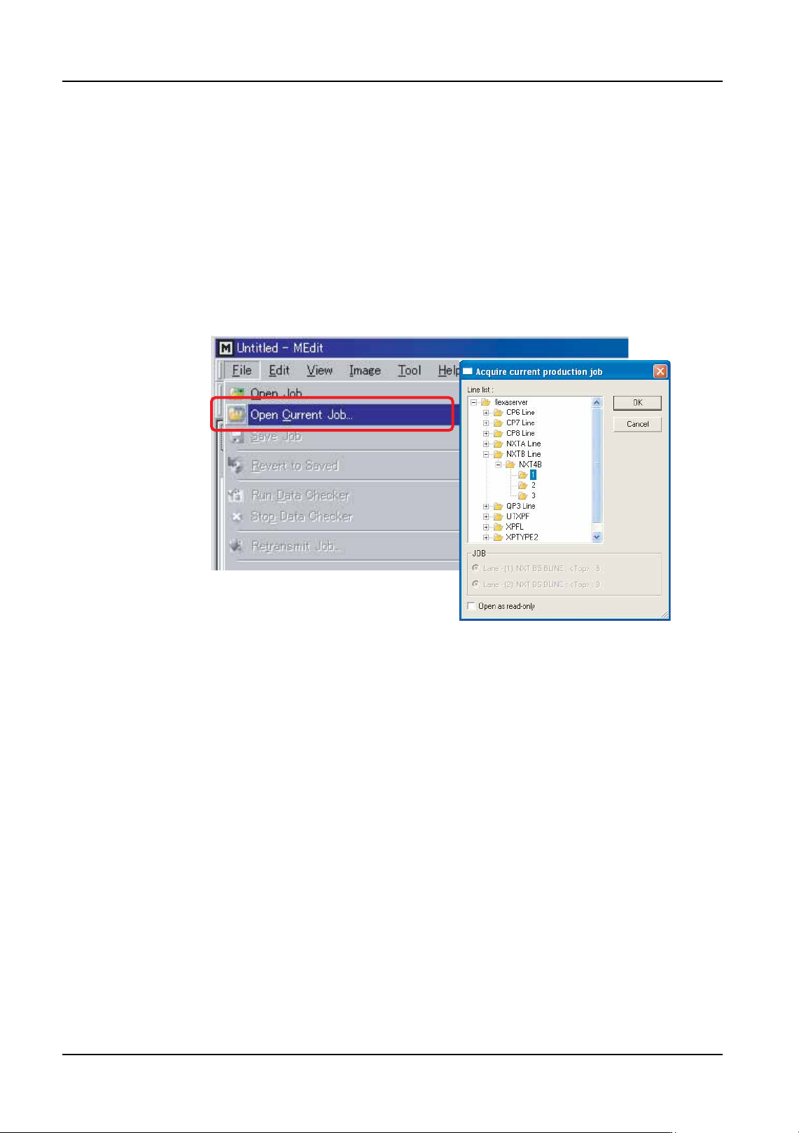
By following the procedures below, the job in the global directory that matches the job that
is currently in the machine is opened. When this is performed, changes made to the job
can be sent to the machine as well as being saved in the global job.
1. Click [Start] and then point to [Programs] - [Fuji Accessory Software] and then click
[MEdit]. MEdit is started and the MEdit window displays.
2. Click [Open Current Job] from the [File] menu. The [Acquire current production job]
dialog box displays.
Note: It is possible to open the same job with the [Open Job] command but if this command is
used, then changes cannot be sent to the machine.
3. Double-click the line with the machine for the job to be edited and then double-click the
machine name to display the modules. Select the module on which the job is to be
edited. The name of the job in the module is automatically displayed in the [JOB] group
box.
Note: If the relevant machine is not displayed in the line, check the settings in [Line display
settings] in Fuji Flexa. If necessary, change the settings so that the relevant line is
displayed.
4. If necessary, select the lane on the module with the job to be edited.
5. Click [OK] and the specified data from the job is opened.
Once the job is opened, it can be edited or tested. For procedure on editing items in MEdit,
refer to the MEdit Operation Manual. The procedures for testing a job are provided in a later
section.
Once the job has been edited/tested, retransmit the edited data back to the machine.
6.3 Correcting vision errors sent from the NXT
From NXT V2.81 and higher, it is possible to make settings that if a vision error occurs for
a particular feeder position, then the vision error image will automatically be sent to the
Accessory Software Server. In Accessory Software, the image can then be opened with
VPDplus and used to check the error condtion and make any corrections as necessary.
NXTEJM010Ea

QD004-18 6. Editing Jobs on the Machine (MEdit)
NXT Programming Manual 155
The data is then sent back to the job in the global server. Once it has been saved back in
the job, MEdit is then used to retransmited the edited job back to the machine. This function
is very useful to help troubleshoot vision data issues with parts that have intermediate vision
errors.
Note: It is not recommended to make settings so that any vision error is set to the Accessory
Software Server for all slots. This is due to the fact that when a vision error occurs and the
image is to be saved to the Accessory Software Server, the module pauses production
while the image is being sent to Accessory Software. If many vision errors occur, then
production can be delayed while waiting for the images to be sent to the server. This
function is mainly designed to be a troubleshooting tool only.
6.3.1 Specifying vision error images to be saved for certain
positions (from NXT V2.81)
If a particular part has frequent vision errors during production, it is possible to specify that
vision error images for that part to be sent to the Accessory Software Server. There are a
few important points that should be addressed when using this function.
• A maximum of 255 images can be saved at the Accessory Software Server.
• The module pauses production while error images are being sent and saved to
the Accessory Software Server.
1. Start Accessory Software and select the module for the machine from which to save
vision error images in Floor Monitor.
2. With the module in question selected, click the vision processing error analysis icon (the
green icon with the picture of a part) for the machine from which to receive vision error
images. The [Vision processing error analysis] screen is displayed.
3. Click [Vision processing setting] at the top right of the [Vision processing error analysis]
screen. A list of used feeder positions in the selected module is displayed.
4. Select the checkboxes for the positions for which to save vision error images.
Note: If [Detailed Settings] is clicked, it is possible to make special settings for which error images
and under what conditions are images sent to Accessory Software for positions. It is even
possible to specify that only certain errors are to be sent.
5. Click [Apply] to enable the settings.
Note: If the power to the machine is turned off or a new job is transmitted, these settings are
cleared.
Note: When a vision processing error occurs at an alternate feeder, the image is saved based on
the settings specified for the original feeder.

6. Editing Jobs on the Machine (MEdit) QD004-18
156 NXT Programming Manual
6.3.2 Viewing saved vision error images
Once an error image has been sent to Accessory Software, it can be displayed in any client
accessing Accessory Software. The details of the error and the image are displayed by
following the procedures below.
1. From Floor Monitor, select the module from which to view error images.
2. Click the vision processing error analysis icon for that machine. The [Vision processing
error analysis] screen is displayed with information for all of the saved images for the
selected module.
• Click [Enlarge] below an image to display that image larger.
• Click the blue text for the error code to display details about that error code.
• If there are more pictures than that can fit on one page, multiple page numbers
are displayed at the bottom of the page. Click the other page number to display
the images for that page.
• The image can be opened/saved by clicking on it. If VPDplus and VPDplus
launcher have been installed on the computer, then the image is opened in
VPDplus and the vision data can be edited.
6.3.3 Opening and editing vision data using saved images
If VPDplus and VPDplus Launcher have been installed on the computer accessing the
Accessory Software, then it is possible to open and edit the vision data for the part using
VPDplus and then reflect any changes back to the job in the server. It is important to note
the following two points.
• VPDplus must be installed on the computer. If the VPDplus license in not
available/purchased, then only the basic editing functions can be used. If a
license for VPDplus is available and the license is present, then those functions
for that license can be used (such as fit and vision test).
• VPDplus Launcher must be installed on the computer. This software links the
images to the shape data and to VPDplus. This software is available from the
download section of the Accessory Software website. If not installed, then
download and install it before attempting to open an image.
1. From Floor Monitor, select the module from which to view error images and then click
the vision processing error analysis icon for that machine. The [Vision processing error
analysis] screen is displayed with information for all of the saved images for the selected
module.
2. Display the image of the part to be edited with VPDplus.
3. Click the image and a [File Download] dialog box is displayed.
4. Select [Open] and the image is opened using VPDplus.
5. Edit the data as necessary. For details on editing items in VPDplus, refer to the VPDplus
Operation Manual or online help.
Note: If using a licensed version of VPDplus, be sure to perform a vision test of the edited settings
before saving them back to the job and restarting production.