FUJI NXT Programming Manual QD004-18.pdf - 第197页
QD004-18 6. Editing Jobs on the Machine (MEdit) NXT Programming Manual 187 and claws are present. 24. Click [Measure] to begin the pickup height test. 25.The results of the test are displayed and the Z of fset is automat…
6. Editing Jobs on the Machine (MEdit) QD004-18
186 NXT Programming Manual
Checking and editing the pickup height for a tray.
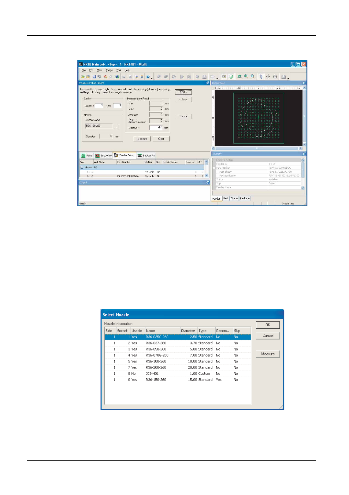
22.The [Measure Pickup Height] step is displayed. Specify the cavity position on which to
perform the pickup test (a part must be present in the cavity) in the [Cavity] group.
Note: Trays have a certain amount of warp. Therefore, the measurement should be performed
at multiple cavities to determine the optimum pickup height. (Fuji recommends measuring
the center cavity and the 4 corner cavities.)
23.If it is necessary to specify a particular nozzle (the nozzle that is to be used in the job is
automatically selected), then follow the sub-steps below.
a. Click [...] to specify which nozzle or claw (OF head only) to use for the test.
Note: The machine knows which nozzles and claws are present in the module (if a check has
been performed by the machine). In cases where the job-specified nozzle and claws can
be used for the height measurement, that nozzle and claws are automatically selected.
b. Select the nozzle or claws (OF head only) to be used for the measurement in the
dialog box that is displayed and then click [OK].
Note: If the module has not yet performed calibration and does not know what nozzles and claws
are present in the nozzle station, click [Measure] to have the module check which nozzles
NXTEJM023b
NXTEJM017Ea
QD004-18 6. Editing Jobs on the Machine (MEdit)
NXT Programming Manual 187
and claws are present.
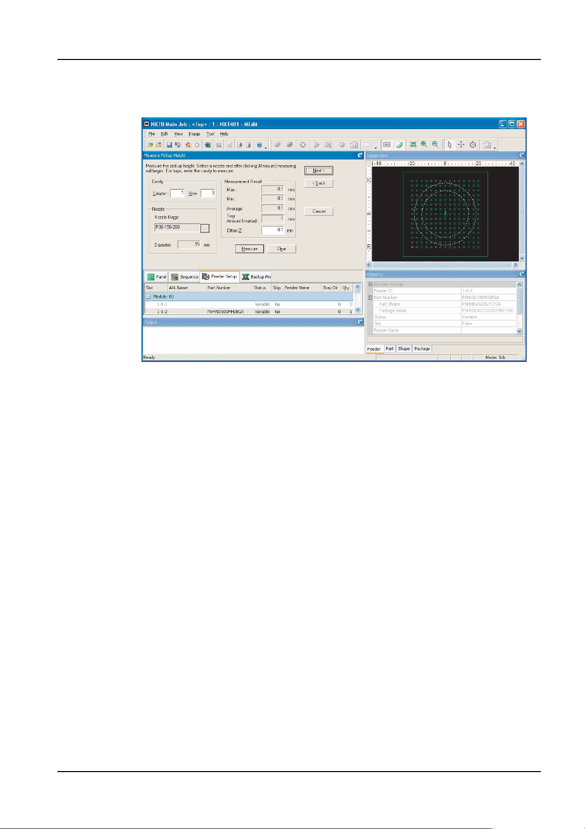
24.Click [Measure] to begin the pickup height test.
25.The results of the test are displayed and the Z offset is automatically determined. It is
possible to manually edit this value.
Note: A dialog box is displayed when a stroke error occurs. Click [Yes] in this dialog box to try
moving the head back down and measure again. The same error occurs if there is no part
in the pickup position. If unsure if a part is present or not, check the part status in the tray.
Caution: If measurement is performed for an OF head, even if the nozzle (claw) does not contact a
part when lowered, the lowest position of the Z-axis is displayed as the result of
measurement. Then, if measurement is performed again, the nozzle (claw) lowers to a
position that is -1.5 mm lower than the result for the previous measurement, so the
measurement value will change greatly. The position at which the result obtained is
approximately the same as the previous result is the position at which the part has actually
been contacted. Due to this, the measurement should be repeated until the result is
approximately the same.
26.Once the Z offset has been determined and the results are acceptable, click [Next].
NXTEJM024Ea
6. Editing Jobs on the Machine (MEdit) QD004-18
188 NXT Programming Manual
Sending changes back to the module.
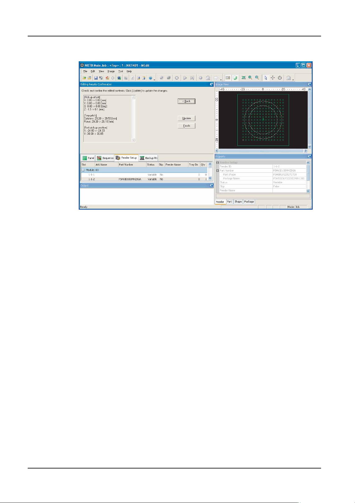
27.The offset results for the pickup position test are displayed. Check the results and if the
results are acceptable, click [Update] to send the changes back to the job. It is possible
to click [Back] to return to previous steps of the pickup test.
28.Click [Finish] to complete the test. If no changes were made, then the test is completed
at this point. If there were changes, then the following steps are performed.
29.A dialog box to specify to which modules to transmit the data is displayed. Select the
modules to which to sent the changes to the job data back and then click [OK]. Note
that if the same part is present in multiple modules, it is important to select all of the
modules that have the same part.
30.A dialog box is displayed asking if Data Checker should be run or not. Click [Yes] to
check the job data with data checker.
31.A dialog box is displayed with the results of the retransmission. Check the results and
click [Close] if transmission was successful.
NXTEJM025Ea