FUJI NXT Programming Manual QD004-18.pdf - 第195页
QD004-18 6. Editing Jobs on the Machine (MEdit) NXT Programming Manual 185 14.Check the pickup position in the X- and Y-di rection using the displayed image . If the pickup position needs to be moved, click the po sition…
6. Editing Jobs on the Machine (MEdit) QD004-18
184 NXT Programming Manual
Checking and editing the tray pitch and X- and Y-positions.
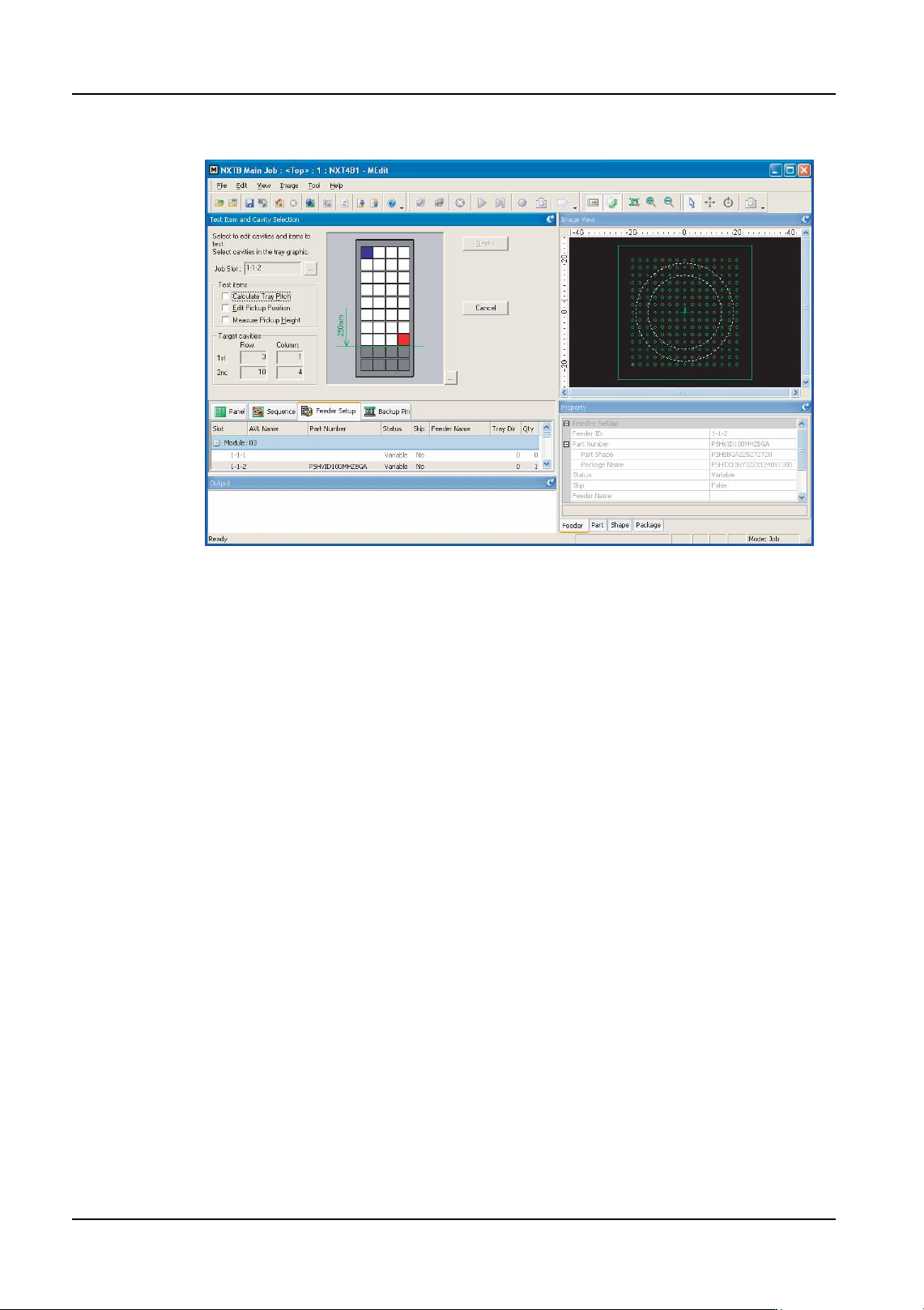
11.If the [Calculate Tray Pitch] option is selected, then specify two possible pick positions
in the tray. If the [Edit Pickup Position] is only selected, then select only one pickup
position. [Next] is not available until the required positions have been selected.
Note: It is not necessary to select the first and last pickup positions. Any position in the tray can
be selected. However, if measuring the tray pitch, the measured results will be better if the
two selected cavities are the furtherest from each other. Tray positions past the top 250
mm of the tray cannot be selected due to restrictions in the travel range of the mark camera.
12.Click [Next] and the [Edit First Cavity] step is displayed. If the tray pitch test is not being
performed and the edit pickup position is being performed, then go to step 19. If the first
pickup position data is not being edited and pickup height is being measured, then go to
step 22.
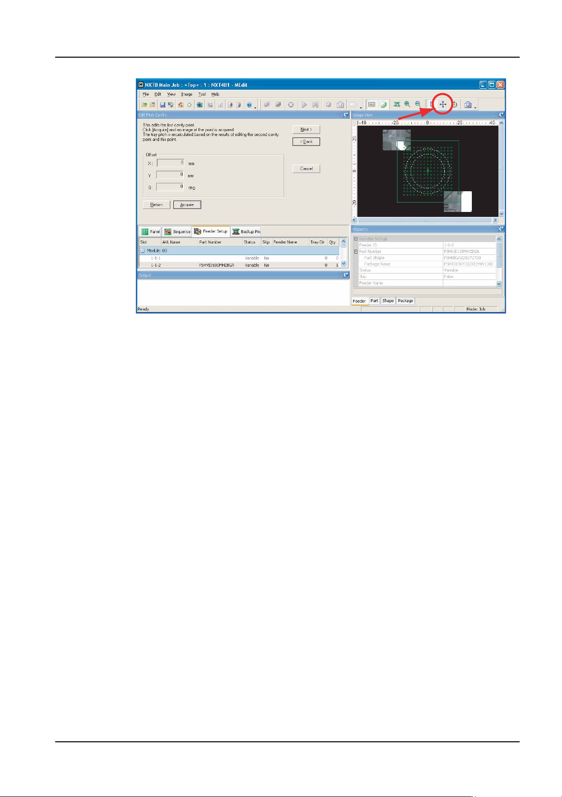
13.Click [Acquire] to take a picture of the part in the first specified slot in the tray. A picture
of the part is taken and displayed.
NXTEJM021Ea
QD004-18 6. Editing Jobs on the Machine (MEdit)
NXT Programming Manual 185
14.Check the pickup position in the X- and Y-direction using the displayed image. If the
pickup position needs to be moved, click the positioning button (the button with the four
arrows) and then click in the image of the graphic at which the pickup should be
performed (the [Offset] values are automatically changed).
15.When the pickup position for the part is correct, click [Next].
16.The step for the second specified cavity is displayed. Click [Acquire] to take a picture of
the part in the second specified cavity in the tray. A picture of the part is taken and
displayed.
17.Check the second pickup position in the X- and Y-direction using the displayed image.
If the pickup position needs to be moved, click the positioning button (the button with the
four arrows) and then click in the image of the graphic at which the pickup should be
performed (the [Offset] values are automatically changed).
18.When the pickup position for the part is correct, click [Next]. If the first pickup position
data is not being edited and pickup height is being measured, then go to step 22. If none
of these are being measured, then go to step 27.
Checking and editing the pickup position for a tray.
19.The step for editing the pickup position is displayed. Click [Acquire] to take a picture of
the part in the specified slot in the tray. A picture of the part is taken and displayed.
20.Check the pickup position in the X- and Y-direction using the displayed image. If the
pickup position needs to be moved, click the positioning button (the button with the four
arrows) and then click in the image of the graphic at which the pickup should be
performed (the [Offset] values are automatically changed).
21.When the pickup position for the part is correct, click [Next]. If the pickup height test is
not being performed, go to step 27.
NXTEJM022Eb
6. Editing Jobs on the Machine (MEdit) QD004-18
186 NXT Programming Manual
Checking and editing the pickup height for a tray.
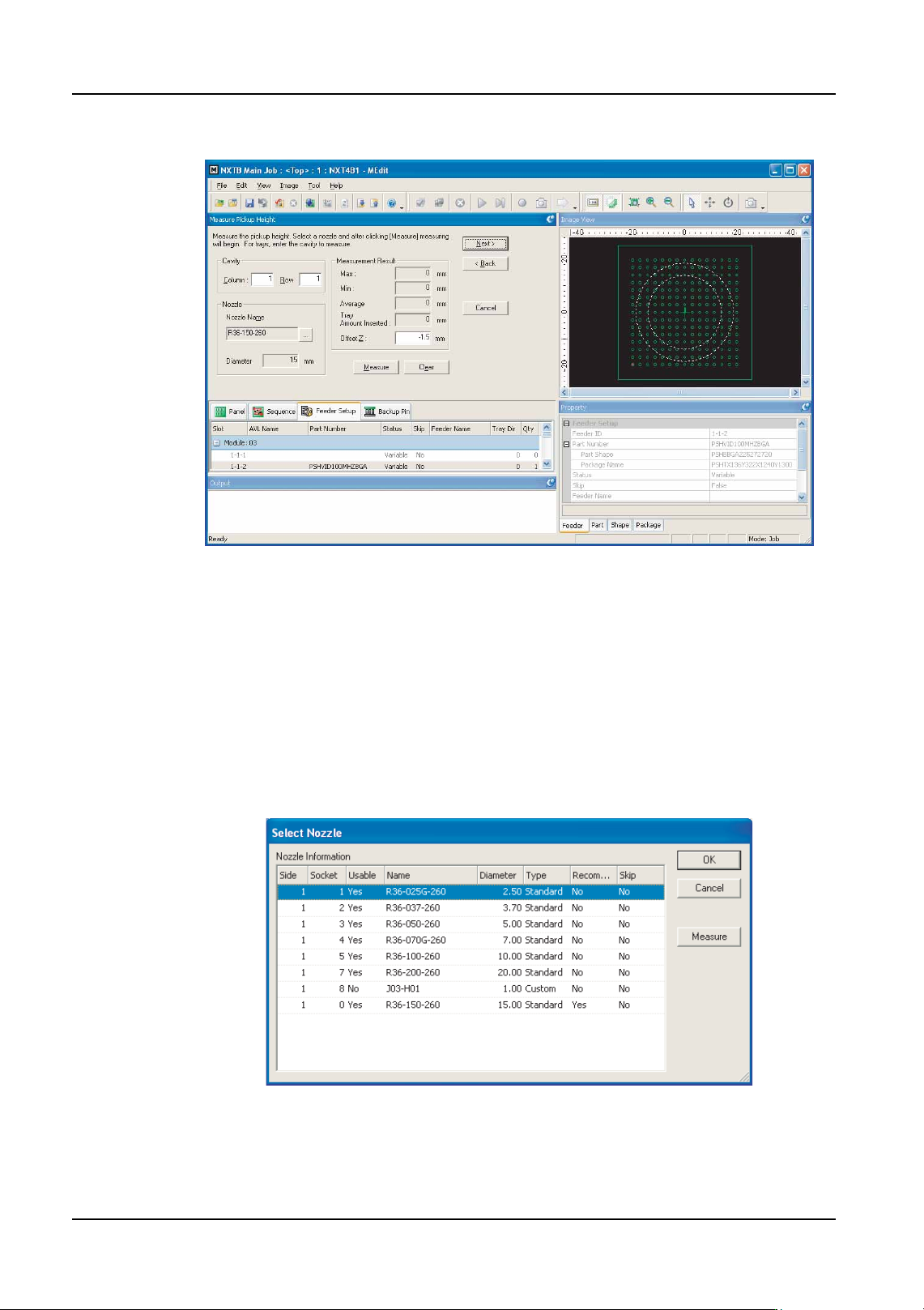
22.The [Measure Pickup Height] step is displayed. Specify the cavity position on which to
perform the pickup test (a part must be present in the cavity) in the [Cavity] group.
Note: Trays have a certain amount of warp. Therefore, the measurement should be performed
at multiple cavities to determine the optimum pickup height. (Fuji recommends measuring
the center cavity and the 4 corner cavities.)
23.If it is necessary to specify a particular nozzle (the nozzle that is to be used in the job is
automatically selected), then follow the sub-steps below.
a. Click [...] to specify which nozzle or claw (OF head only) to use for the test.
Note: The machine knows which nozzles and claws are present in the module (if a check has
been performed by the machine). In cases where the job-specified nozzle and claws can
be used for the height measurement, that nozzle and claws are automatically selected.
b. Select the nozzle or claws (OF head only) to be used for the measurement in the
dialog box that is displayed and then click [OK].
Note: If the module has not yet performed calibration and does not know what nozzles and claws
are present in the nozzle station, click [Measure] to have the module check which nozzles
NXTEJM023b
NXTEJM017Ea