FUJI NXT Programming Manual QD004-18.pdf - 第99页
QD004-18 4. Part Data Settings NXT Programming Manual 89 Process - Nozzle Minimum Diam eter Specify the minimum no zzle diameter which can be used to pick up the part with the shape. Maximum Diameter Specify the maximum …
4. Part Data Settings QD004-18
88 NXT Programming Manual
Width Tolerance
Specify the width tolerance of element leads.
Length
Specify the length of the element leads.
Length Tolerance
Specify the length tolerance of the element leads.
Center Tolerance
Specify the bend tolerance for the element leads.
4.3.4 Shape Process details
Body
Location Pin Length
Specify the length in mm of any locating pins on the shape if they are present. This setting
is especially required if using the insertion pressure function.
Part Pattern Tolerance X
This item is enabled for when Vision Type 240 to 242 is set in VPDplus. Check the help file
in VPDplus for more details.
Part Pattern Tolerance Y
This item is enabled for when Vision Type 240 to 242 is set in VPDplus. Check the help file
in VPDplus for more details.
Lead
Check Point
Specify the point on the leads (measured from the end of the lead) that is checked. If 0 is
specified, the check occurs at the lead's 30% position. The following settings represent
general guidelines for various parts.
Quantity Check Limit
Specify the number of leads on leaded parts which must be detected for the part to pass
inspection. If this is set to 100%, all the leads must be detected. If set to 90%, 90% of the
leads must be detected. This is normally set to 100%.
Lead Brightness
This sets the brightness level for leads (bumps) that is used when automatic determination
of lead brightness is difficult. Correspondingly larger values should be specified for brighter
leads. When set to 0, brightness is determined automatically.
Part Type Setting
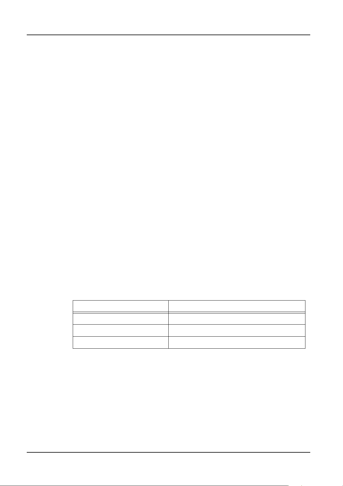
SOP / QPF 10 to 90% (standard setting: 30%)
PLCCs / SOJ 50 to 70% (standard setting: 60%)
BGA / Flip Chip 50%

QD004-18 4. Part Data Settings
NXT Programming Manual 89
Process - Nozzle
Minimum Diameter
Specify the minimum nozzle diameter which can be used to pick up the part with the shape.
Maximum Diameter
Specify the maximum nozzle diameter which can be used to pick up the part with the shape.
Name
Set this parameter for special nozzles. Although a nozzle is normally identified by the size
of its circular pickup area, a name is specified for special non-circular nozzles.
Load Check
Specify whether to check the nozzle load at constant intervals during production.
Process - Head
Target Heads
Specify the usable heads when limiting the heads to be used for placing parts.
Process - Pick
Do Auto Offset
Specify whether automatic compensation is performed for pick-up offsets. When No is
specified, the center of the part is used as the part pick-up position. However, pick-up at
the part center may not be possible for various reasons. To counter this, the amount of
offset is calculated by vision processing and this information can be fed back to the pick-up
position so that the part can be picked up at its center.
If parts are not being correctly picked up at their centers and "Do Auto Offset" is set to Yes,
the offset between the nozzle center and the part center is calculated so that subsequent
parts can be correctly picked at their centers.
Offset X / Offset Y
Normally, parts are picked up at the center of their bodies. However, for some odd shaped
parts this is not possible. If necessary, specify an offset from the center of the packaging
cavity to the pickup point on the body for the part to pick-up such parts. If 0 is entered, the
pickup point is the center of the packaging cavity. The value specified in Offset X, Y are the
point at which the part is picked up, and the center of the camera field of view is aligned
with the center of the nozzle during vision processing.
Offset Z
Specify an up or down offset for the pickup position of the part in a feeder cavity.
Tray Pick Offset Z
Specify an up or down offset for the pick-up point of the part in a tray cavity.
Soft Pick Speed
Specify the percentage of the maximum possible Z-axis speed at which the part is carried
after pick-up.
Enable Pressure Sensor
This specifies whether or not the part using the shape data is picked with 220 gf when using
a pressure sensor equipped head. If set to "Yes" the part is picked using pressure control,
4. Part Data Settings QD004-18
90 NXT Programming Manual
while if the setting is "No" the pressure control is not used when the part is picked. This
setting is only applicable for heads with this sensor. This setting has priority over soft pick-
up settings.
Do Prerotation
This setting is ignored by the NXT. Prerotation is automatically performed on heads that
support this function.
Do Prerotation for Custom Nozzle
Specify whether or not to rotate parts to (or near to) the placement angle prior to vision
processing when using custom nozzles. This setting is only valid for the H01, H02, and G04
heads.
Do Part Height Check
Specify whether or not to perform a height check of the part. This setting is only used if the
head can check the part height (for example, H12SQ).
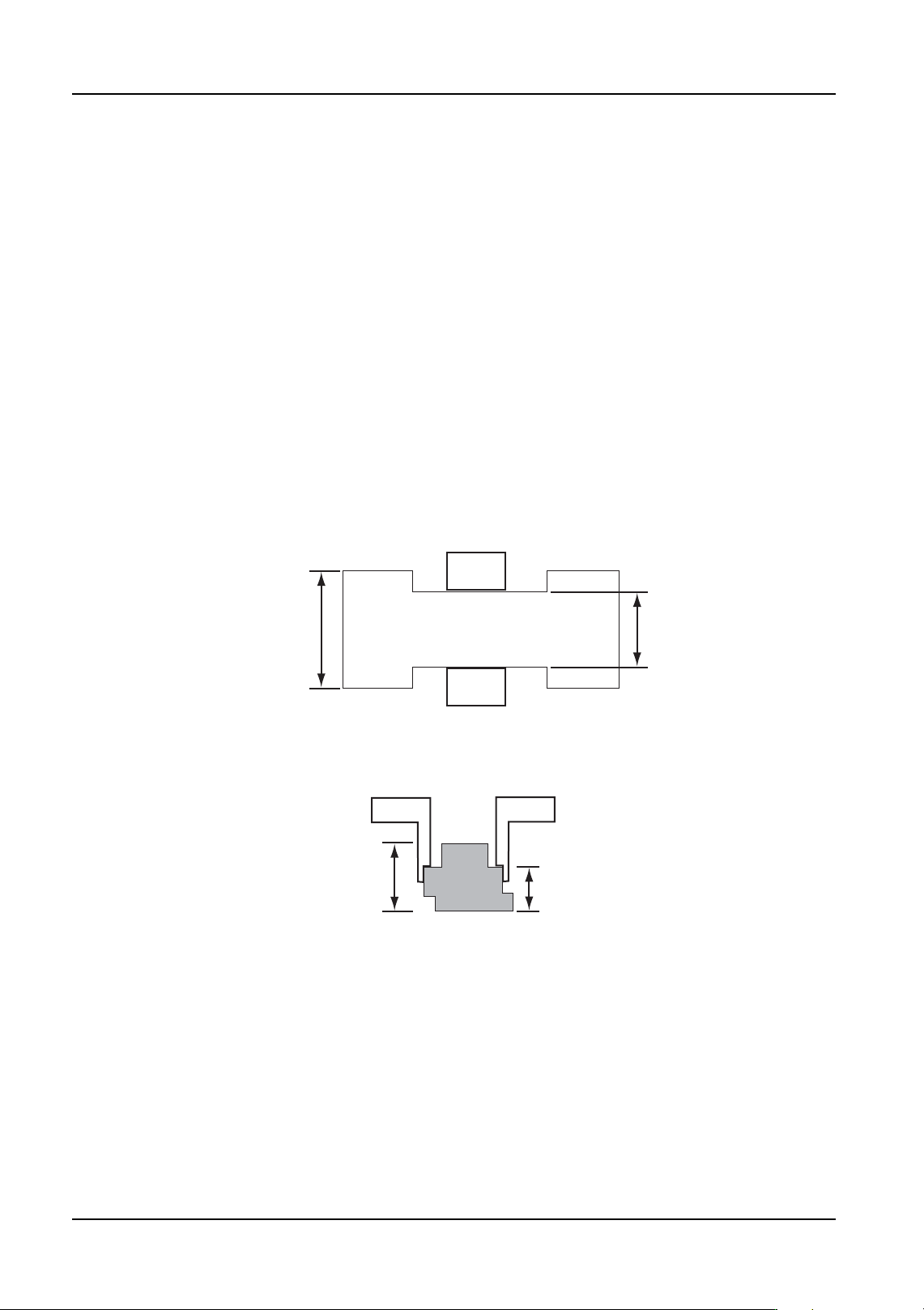
Clamp Width
Specify the width of the part at the clamping position. This setting is only valid for the OF
head.
Actual Pickup Body Height
Specify the height of the part at the clamping position.
Clamp Margin
Specify the gap between the claw width during clamping and the actual claw width. This
setting is only valid for the OF head.
Part Body
Claw
Width
01PRG063E
Claw
Clamp Width
Body Height
01PRG064E
Claw
Actual Pickup Body Height
Claw
Part Body