FUJI NXT Programming Manual QD004-18.pdf - 第48页
3. Job Builder QD004-18 38 NXT Programming Manual 5. There a re several tabs at the bottom of the [Machin e Configura tion] pane. S elect the [Process Options] tab and the process options for the machin e display. 6. Ent…

QD004-18 3. Job Builder
NXT Programming Manual 37
5. Click in the blank data cell for “Board” and select the “0” from the drop-down list.
6. Press the right arrow key to move to the type data cell, and select “Panel Edge” from the
drop-down list.
7. Press the right arrow key to move to the level data cell, and select “Panel” from the drop-
down list.
8. Press the right arrow key to move to the reference data cell, and enter a unique
reference number.
9. Press the right arrow key to move to the X-position data cell, and enter the X-position
for the panel edge to be checked. This position must be inside of the panel. Refer to
the “Cautions regarding panel edge position” section below for information about the
panel edge checking position.
10.Press the right arrow key to move to the Y-position data cell, and enter the Y-position
for the panel edge to be checked. Generally, this position will be 12 mm and is the Y-
position that the felt paper is usually applied on the backup plate. This position must be
inside of the panel. Refer to the “Cautions regarding the panel edge check position”
section below for information about the panel edge checking position.
11.Press the right arrow key to move to the mark name data cell, leave this field blank.
12.Enter any other information as necessary.
Note: It is not possible to make 2 or more panel edge check sequences for a panel.
Cautions regarding the panel edge check position
Be sure to note the following caution points about the panel edge check position.
• The X- and Y-position must be inside of the panel, but very close to the edge
position to be checked (within the scanning area).
• Always specify a section with a straight line of the panel edge. Do not include a
cut-out section in the scan area as panel play may affect positioning.
• When panel rotation is specified, set the coordinates based on the panel
orientation at the time of transportation on the conveyor.
• Specify a location that does not contain any bright objects such as backup pins,
for times when there is no panel on the conveyor. Nor place any bright items in
the specified area (such as backup pins, soiled/grease areas, soft backup pin
tips).
Making job machine configuration settings in Fuji Flexa
Generally the machine configuration settings for the panel edge will be appropriate and do
not need to be changed. Follow the prodecures below if the settings need to be changed.
1. Select the [Top] or [Bottom] tab from the job information bar depending on the side of
the panel the machine to be edited is located.
2. Double-click the name of the line to display the machines in that line.
3. Double-click the name of the machine for which to set the auto backup pins.
4. Double-click [Configuration] under the machines name and a window displays in the
data area.
3. Job Builder QD004-18
38 NXT Programming Manual
5. There are several tabs at the bottom of the [Machine Configuration] pane. Select the
[Process Options] tab and the process options for the machine display.
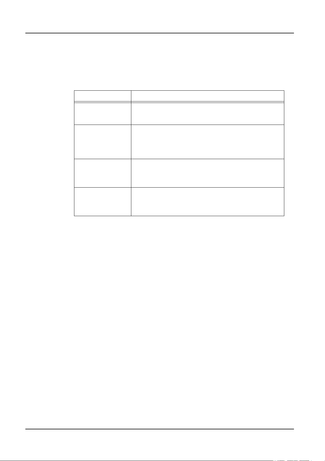
6. Enter the appropriate panel stopping position correction settings process settings for the
machine if the panel stopping position correction function is turned on. Refer to the table
below for information on these settings.
Setting Description
Scan Area X/Y This specifies the size of the area in the X- and Y-direction
checked for the panel edge when correcting the panel
stopping position.
Shutter Speed This setting specifies the shutter speed used by the mark
camera when checking for the panel edge. The larger the
value, the slower the shutter speed and the image
becomes brighter. Generally, the default setting is
appropriate.
Color Specify which lighting should be used to check for the
panel edge. Different settings will be required depending
on the color of the panel. Generally, the default setting is
appropriate.
Pattern Specify which lights should be used to check for the panel
edge. Different settings will be required depending on the
color of the panel. Generally, the default setting is
appropriate.
QD004-18 3. Job Builder
NXT Programming Manual 39
3.4.3 Package-on-Package placement (from NXT V4.10)
The package-on-package (PoP) placement function uses pressure control to stack parts on
top of parts that have already been placed.
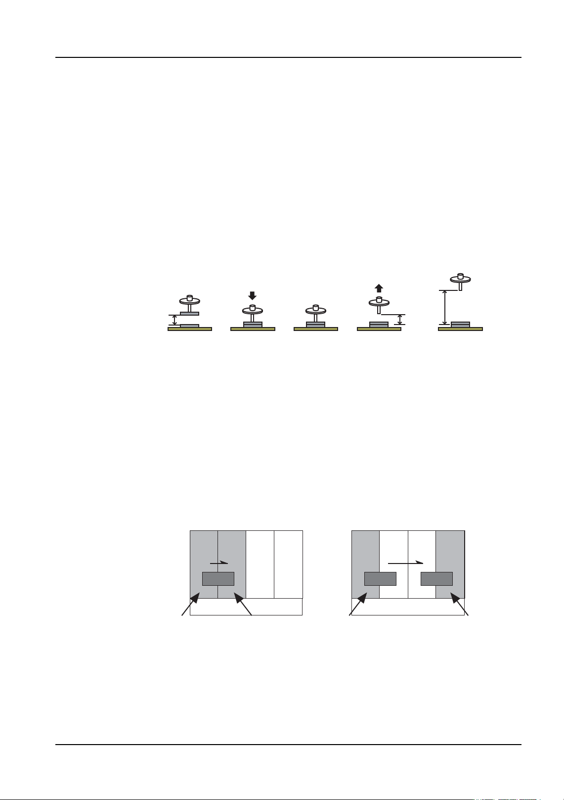
Note: The distance used for the placing pressure control start height (H) varies depending on
whether the lower and upper parts are stacked at the same module or at different modules.
* If parts are stacked at the same module, H is equal to the top of the lower part that has
already been placed plus 2.5 mm.
* If parts are stacked at different modules, H is equal to the premounted parts height
specified for the module at which the lower part is placed.
Restrictions:
If PoP placement is performed at paired modules, the lower part and upper part of the stack
must be placed at the same module within the pair (see the figure on the lower left).
However, the lower part can be placed at a module within a set of paired modules, and then
the upper part can be placed at a different module within a different set of paired modules
(see the figure on the lower right).
(1) The nozzle (Z-axis) is lowered at the specified speed from the placing
pressure control start height (H).
(2) The nozzle places the part, pushing down with the specified pressure.
(3) The head pauses for the specified time.
(4) The nozzle (Z-axis) rises to the placing pressure control end height (same
as H) at the specified speed. After reaching the placing pressure control
end height, the nozzle continues to rise at normal speed.
01PRG-0035
(4)(3)(2)(1)
HH
01PRG-0037E
Lower part is placed Upper part is placed
Lower part is placed
Upper part is placed
Paired module
Paired module Paired module
PoP placing is not possible PoP placing is possible