FUJI NXT Programming Manual QD004-18.pdf - 第112页
4. Part Data Settings QD004-18 102 NXT Programming Manual 4.5 P_pattern Details The p_pattern specifies the way the lead a ppear s to the vision processin g system and how the processing of the lead information for the p…

QD004-18 4. Part Data Settings
NXT Programming Manual 101
4.4.4 Package Process details
Tape
None of the process settings that display when tape packaging is selected are used by the
NXT.
Reel Diameter
Specify the reel diameter if using feeders with reel holders so the optimizer can properly
allocate the feeders. This is only used by Fuji Flexa when determining and checking the
feeder setup. The machine does not actually use this setting.
Tray
Tray Type
Specify the type of tray being used.
Tray Cavity Information
Specify the cavity information (I.e. which cavities have parts and which do not) for trays.
Setting Description
Matrix-Dump The tray type is processed as "No Matrix-Dump" if this is
selected. This setting is only used if a tray unit with a remover
is used.
No Matrix-Dump If the machine fails to pick-up a part, it will attempt to pick up
the part from the same position the specified number of
recovery times. If pick-up is still unsuccessful, the machine
proceeds to pick up parts from the next pick-up position.
This setting is only used if a tray unit with a remover is used.
No Matrix Automatic discharge of the tray is not performed. Aluminum or
other customer-specific trays that are heavier than normal
cannot be lifted by the remover's vacuum pad. Instead, this
mode is selected and the tray is changed by hand. If the
machine fails to pick-up a part, it will attempt to pick up the part
from the same position the specified number of recovery times.
If pick-up is still unsuccessful, the machine proceeds to pick up
parts from the next pick-up position.
Ref Cavity Info-Dump Specify this item to have settings made at Tray Cavity
Information used for pick-up information. If the machine fails to
pick-up a part, it will attempt to pick up the part from the same
position the specified number of recovery times. An error
occurs and the machine stops if it has not picked up the part
when the recovery limit is reached.
This setting is only used if a tray unit with a remover is used.
Ref Cavity Info Specify this item to have settings made at Tray Cavity
Information used for pick-up information. The tray is removed
by hand (as is the case when "No Matrix" is selected), when
parts run out.
4. Part Data Settings QD004-18
102 NXT Programming Manual
4.5 P_pattern Details
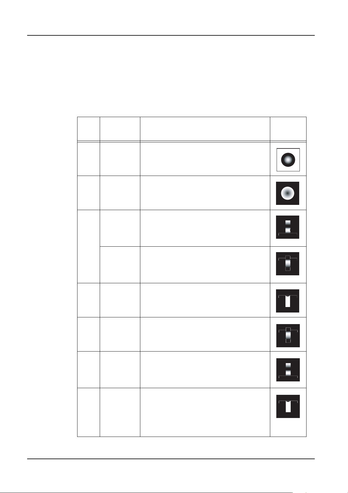
The p_pattern specifies the way the lead appears to the vision processing system and how
the processing of the lead information for the part is to be performed. In addition, it is
necessary to be aware that the placing position is affected by the specified p_pattern.
4.5.1 P_patterns used for the NXT
The following p_patterns are valid for use on the NXT with the frontlight system.
P_
patte
rn
Example
Part
Details Lead
Appearan
ce
1 Bump parts White body parts
2 Bump parts
Column
parts
Black body parts
4 SOIC Lead tip and width detection is performed.
The results are used for positioning
information. Lead length is not used for
positioning information with p_pattern types
12 and 14.
SOJ The lead ends do not display well, but lead
length is used for acquiring position
information. Lead length is not used for
acquiring positioning information with
p_pattern type 12.
6 LCC Leads point into the body and the lead tips
and width are detected. These results are
used for positioning information.
12 PLCC Because the lead ends do not display well,
lead width only is used for acquiring position
information. In some cases, processing is
more stable when using p_pattern type 14.
14 QFP Lead tip and width detection is performed.
Because the lead width direction positioning is
only required for determining the positioning,
only the lead width direction results are used
for positioning information.
16 LCC Leads extend into the body and the lead tips
and width are detected. These results are
used for positioning information. Because the
lead width direction positioning is only
required for determining the positioning, only
the lead width direction results are used for
positioning information.
QD004-18 4. Part Data Settings
NXT Programming Manual 103
4.5.2 P_patterns not supported by the NXT
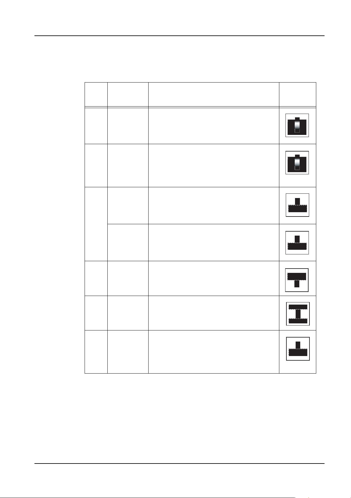
The following p_patterns are not valid for the NXT due to background conditions and/or the
use of backlighting.
P_
patte
rn
Example
Part
Details Lead
Appearan
ce
24 SOJ Used only with a white background. Lead tip
and width detection is performed. The results
are used for positioning information. Lead
length is not used for positioning information
with p_pattern type 34.
34 PLCC Used only with a white background. Lead tip
and width detection is performed. Because
the lead width direction positioning is only
required for determining the positioning, only
the lead width direction results are used for
positioning information.
3 SOIC Used only with backlighting. Lead tip and
width detection is performed. The results are
used for positioning information. Lead length
is not used for positioning information with
p_pattern types 11 and 13.
SOT Used only with backlighting. Lead tip and
width detection is performed. The results are
used for positioning information. Lead length
is not used for positioning information with
p_pattern types 11 and 13.
5 PLCC
Socket
Used only with backlighting. The leads point
towards the inside of the body. Lead tip and
width detection is performed. The results are
used for positioning information.
11 TAB Used only with backlighting. Because the
lead tip and base are both connected to the
body, only the lead width is use for positioning
information.
13 QFP Used only with backlighting. Lead tip and
width detection is performed. Because the
lead width direction positioning is only
required for determining the positioning, only
the lead width direction results are used for
positioning information.