FUJI NXT Programming Manual QD004-18.pdf - 第45页
QD004-18 3. Job Builder NXT Programming Manual 35 15.If the [Level] setting for the backup pin is “Loc a l”, then select that row by clicking the gray box to the left of the row. Rig ht-click and select [Edit Part Info].…
3. Job Builder QD004-18
34 NXT Programming Manual
Procedure
1. Select the [Top] or [Bottom] tab from the job information bar depending on the side of
the panel the machine to be edited is located.
2. Double-click the name of the line to display the machines in that line.
3. Double-click the name of the machine for which to set the auto backup pins.
4. Double-click [Configuration] under the machines name and a window displays in the
data area.
5. There are several tabs at the bottom of the [Machine Configuration] pane. Select the
[Process Options] tab and the process options for the machine display.
6. Select “Yes” from the drop-down list from the [Use Auto Backup Pin] setting in the
[Backup Plate] group.
Note: If a special backup plate is required, enter the name of the required backup plate in the
[Backup Plate Name] field on this page.
7. Double-click [Backup Pin] in the [Top]/[Bottom] tab in the job information bar.
8. Select [Display] from the [Format] menu and click the [Backup Pin] tab.
9. Set the desired colors for the top and bottom parts in order to distinquish between them
better in the view and click [OK].
10.Position the pointer in the position in the view that a backup pin is to be set and right-
click.
11.Select [Add Part] from the displayed shortcut menu. The [Add Part] dialog box is
displayed with the X and Y position data specified as the location that the mouse was
right-clicked.
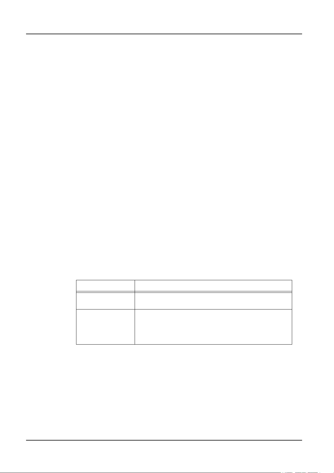
12.Select the level for the backup pin from the [Backup Pin Class] drop-down list. Refer to
the table below for details.
13.If you want to change the default reference name used, click in the [Reference] text box
and specify the new reference name. It is possible to use the default name, as long as
it is not used anywhere else in the job as a reference designator.
Note: It is possible to change other settings in this dialog box if necessary.
14.Click [OK] to register the information in the dialog box.
Setting Description
Global When this is selected, the backup pin is placed at the
specified position in all modules. This is the default setting.
Local When this is selected, the backup pin is placed at the
specified position only in the module placing a specified
part. When this setting is selected, the related part
reference number must be specified in the [Edit Part Info]
dialog box for that backup pin.

QD004-18 3. Job Builder
NXT Programming Manual 35
15.If the [Level] setting for the backup pin is “Local”, then select that row by clicking the gray
box to the left of the row. Right-click and select [Edit Part Info]. Click to button to the
right of the [Ref. list] display and select the reference designator for the part that the
backup pin is to be linked with from the displayed list. Click [OK] and then [OK] in the
[Edit Part Info] dialog box. The backup pin is then linked to the specified part and will be
set in the module that places that part.
Note: It is possible to select multiple parts in the displayed list.
16.Repeat steps 10 to 15 until all of the desired backup pins have been specified for that
side of the panel.
17.Repeat these procedures to make backup pin settings for the other side of the board.

3. Job Builder QD004-18
36 NXT Programming Manual
3.4.2 Specifying a panel edge sequence (from NXT V3.10)
This is used for checking the panel stopping position when the panel stopping position
function is being used on the NXT. It is necessary to have a compatible version of Fuji
Flexa and NXT control software V3.10 or higher and the panel stopping position correction
function must be enabled in the machine configuration in order to use this function. In
addition, if the panel stopping position correction function is turned off in the machine
configuration, then any settings made regarding this are ignored by the machine.
Making machine configuration settings
The following procedures are used to turn on the panel stopping position correction function
for the machine.
1. Double-click the [Internet Explorer] icon on the desktop.
2. Enter the address (URL) "http://<NXT accessory software server name>/fujiweb" and
then press Enter. If the server computer is located and the server is running, a loading
page displays. Once the necessary items have been loaded, the [Home] page displays.
This page provides basic production information for the NXTs.
3. From Floor Monitor, click the machine or module number for the NXT for which Machine
Accessories is to be used. The Machine Accessories log on page is displayed
4. Enter or select a user ID from the drop-down list.
5. Enter the password for the user and click [Log on]. Once connected to the machine, the
top diagram of the picture will match the machine that was selected. In the lower left
side, the menu for possible actions displays. In the lower right side, the details for the
selected item displays.
6. Click [Machine Configuration] from [Menu]. Accessory Software connects to the
machine and receives the machine information. When completed, the settings page
displays.
7. Select [Loader Settings] from the [Category] drop-down list. When a category has been
selected the settings shown under the list automatically change to the selected
category.
8. Select the [ON (Panel Edge)] option for [Panel position correction].
9. Once the settings have been completed, click [Send to Machine] to send the new setting
to the machine. During transmission to the machine, the operation panel will change to
the transmission display. When sending the new setting is complete, a page displays
with that message.
10.Once all changed settings have been sent to the machine, click [Close].
Making a panel edge check sequence in Fuji Flexa
1. Select the [Top] or [Bottom] tab from the job information bar depending on the side of
the panel the panel edge sequence is to be added.
2. Double-click [Coordinate] to display the “All” window.
3. There are several tabs at the bottom of the [Coordinate] pane. Select the [Mark] tab and
the mark sequences are displayed.
4. Scroll to the bottom of the sequences until the last blank line is visible.