FUJI NXT Programming Manual QD004-18.pdf - 第204页
6. Editing Jobs on the Machine (MEdit) QD004-18 194 NXT Programming Manual b. Click [Start] and the h ead is moved by t he machi ne to a position at which the part can be placed on the head an d the main screen is displa…
QD004-18 6. Editing Jobs on the Machine (MEdit)
NXT Programming Manual 193
Performing Vision Processing
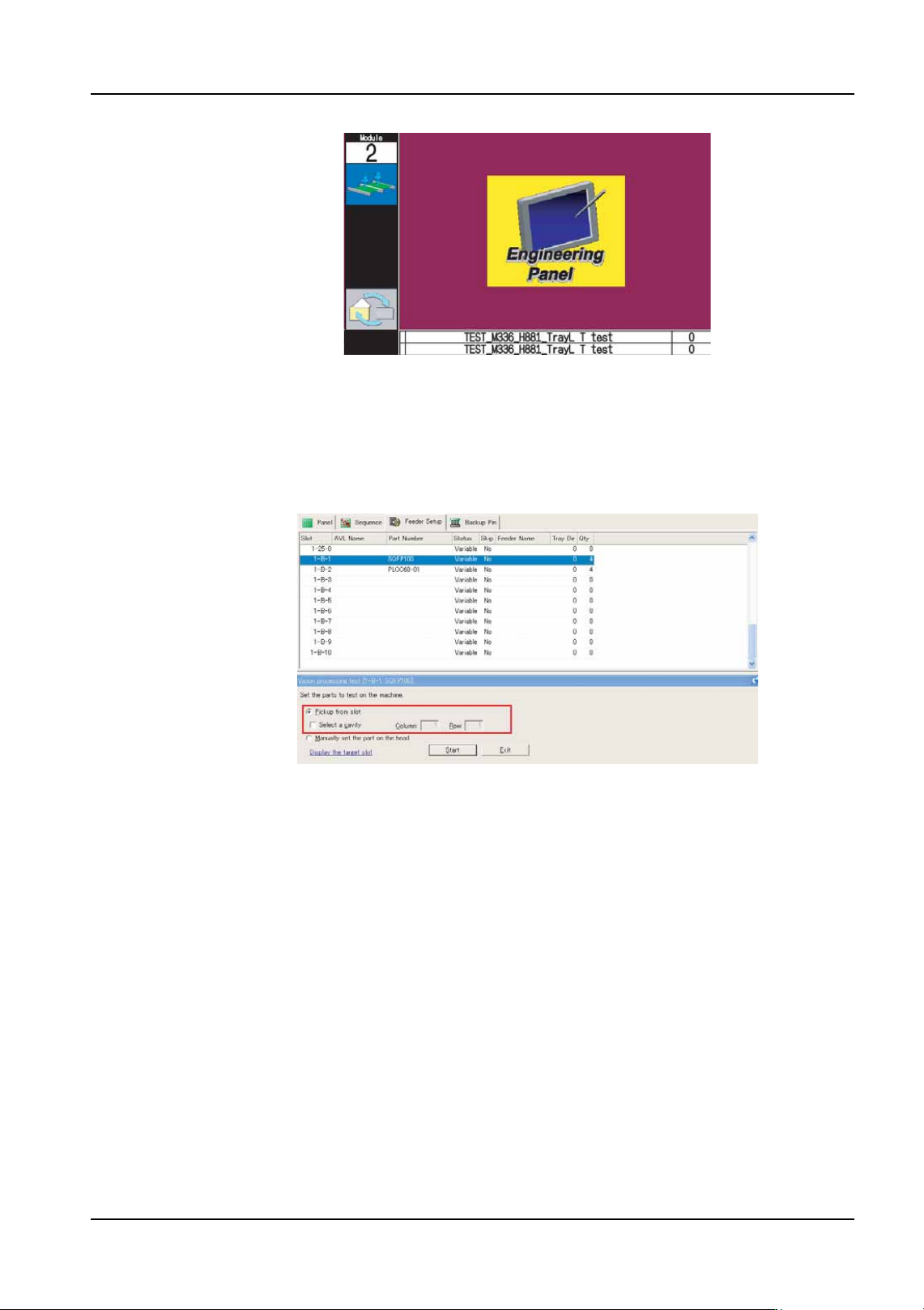
10.If the part to be vision tested is to be picked from a feeder or tray, then follow the
substeps below. If the part is to be placed on the head manually, then proceed to the
next step.
a. Select the [Pickup from slot] option.
b. If the part is a tray part and a specific cavity is to be specified, then select the [Select
a cavity] check box and then specify the pickup position in the [Column] and [Row]
text boxes.
Note: If picking from a tray and the [Select a cavity] check box is not selected, the first pickup
position is automatically determined.
c. Click [Start] and the automatically determined nozzle (claw) is picked and then the
selected part is picked up and vision processed.
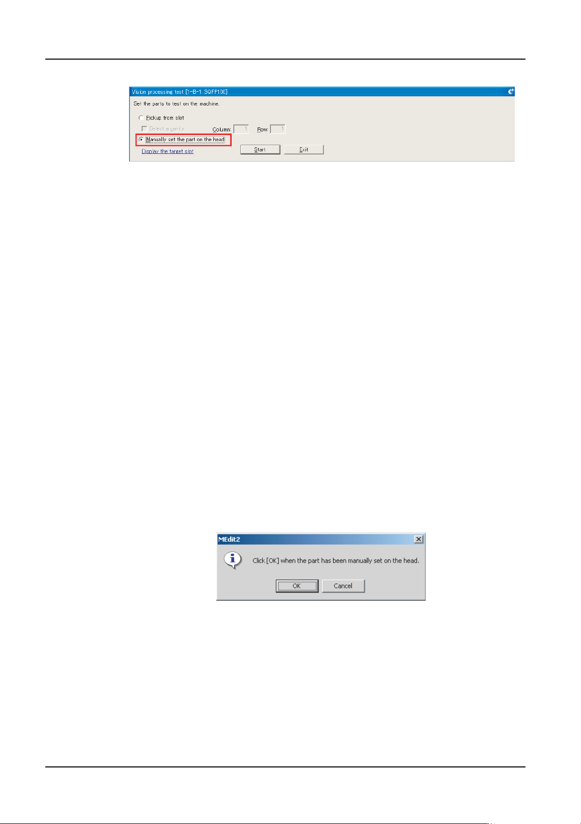
11.If the part to be vision tested is to be placed on the head manually, then follow the
substeps below.
a. Select the [Manually set the part on the head] option.
01PRG-0032
NXTEJM029E
6. Editing Jobs on the Machine (MEdit) QD004-18
194 NXT Programming Manual
b. Click [Start] and the head is moved by the machine to a position at which the part can
be placed on the head and the main screen is displayed.
c. Push EMERGENCY and then open the front door or the side cover and place the part
on the head by hand.
Note: If it is difficult to set the part onto the head in the current position, use the device unclamp
and module unclamp commands in manual mode and pull forward the module.
• When the main screen is displayed, do not perform any operations other than
the device clamp (unclamp) and module clamp (unclamp) commands in manual
mode.
• Do not move the Q-axis when setting parts by hand because the head stops at
an angle aligned for parts pickup. If the Q-axis is moved when parts are set,
there may be interference with the sidelight camera when vision processing is
performed.
• Set the part so that the nozzle is in the center of the pickup position. Pickup
offset must be considered when setting the part. There may be interference with
the side light camera if the part is not centered correctly.
d. Close any opened covers and push back the module and reclamp the device units if
necessary
e. Release the EMERGENCY button.
f. Click [OK] in the dialog box displayed in MEdit and the manually placed part is vision
processed.
Acquiring Images
NXTEJM030E
NXTEJM031E
QD004-18 6. Editing Jobs on the Machine (MEdit)
NXT Programming Manual 195
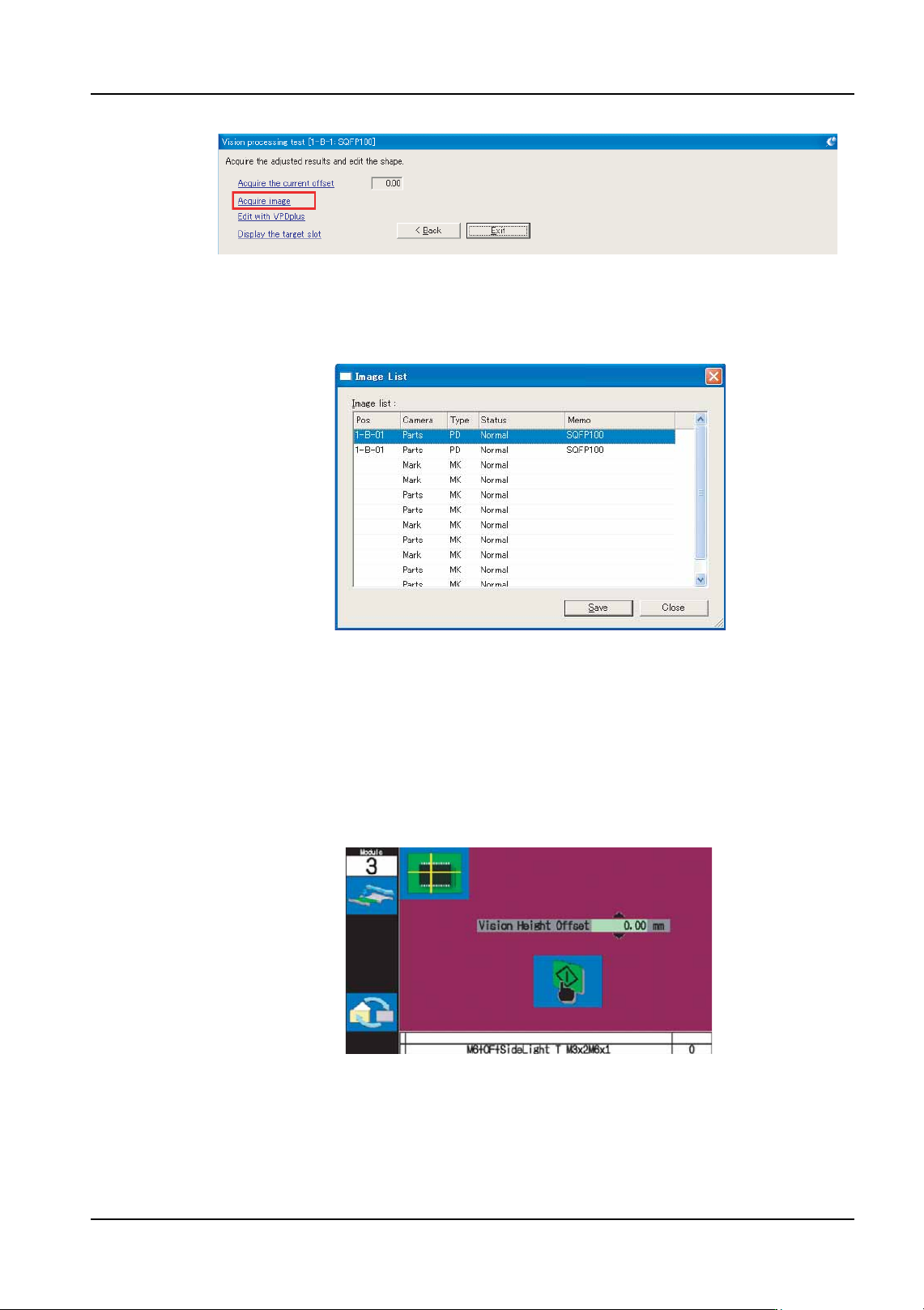
12.Click [Acquire image] from the displayed list. A dialog box with the list of the images is
displayed with the most recent image at the top of the list.
13.Select the top image and click [Save].
Note: When MEdit is used to update the job, it is not possible to acquire the image that existed
immediately before update was performed.
Adjusting the Vision Processing Height (for the side light camera)
14.Follow the substeps below to adjust the vision processing height.
a. Push MONITOR on the operation panel of the module in question.
b. Push the up and down arrow keys to change the setting for the vision height offset.
Specify the desired offset.
c. Push START and vision processing of the part is performed using the specified
setting and the image is displayed.
NXTEJM032E
NXTEJM033E
01PRG-0033