FUJI NXT Programming Manual QD004-18.pdf - 第167页
QD004-18 6. Editing Jobs on the Machine (MEdit) NXT Programming Manual 157 6. Once editing is completed, select [Upd ate Shape Data] from the [File] menu. A confirmation message box is displa yed. 7. Click [Yes] and the …

6. Editing Jobs on the Machine (MEdit) QD004-18
156 NXT Programming Manual
6.3.2 Viewing saved vision error images
Once an error image has been sent to Accessory Software, it can be displayed in any client
accessing Accessory Software. The details of the error and the image are displayed by
following the procedures below.
1. From Floor Monitor, select the module from which to view error images.
2. Click the vision processing error analysis icon for that machine. The [Vision processing
error analysis] screen is displayed with information for all of the saved images for the
selected module.
• Click [Enlarge] below an image to display that image larger.
• Click the blue text for the error code to display details about that error code.
• If there are more pictures than that can fit on one page, multiple page numbers
are displayed at the bottom of the page. Click the other page number to display
the images for that page.
• The image can be opened/saved by clicking on it. If VPDplus and VPDplus
launcher have been installed on the computer, then the image is opened in
VPDplus and the vision data can be edited.
6.3.3 Opening and editing vision data using saved images
If VPDplus and VPDplus Launcher have been installed on the computer accessing the
Accessory Software, then it is possible to open and edit the vision data for the part using
VPDplus and then reflect any changes back to the job in the server. It is important to note
the following two points.
• VPDplus must be installed on the computer. If the VPDplus license in not
available/purchased, then only the basic editing functions can be used. If a
license for VPDplus is available and the license is present, then those functions
for that license can be used (such as fit and vision test).
• VPDplus Launcher must be installed on the computer. This software links the
images to the shape data and to VPDplus. This software is available from the
download section of the Accessory Software website. If not installed, then
download and install it before attempting to open an image.
1. From Floor Monitor, select the module from which to view error images and then click
the vision processing error analysis icon for that machine. The [Vision processing error
analysis] screen is displayed with information for all of the saved images for the selected
module.
2. Display the image of the part to be edited with VPDplus.
3. Click the image and a [File Download] dialog box is displayed.
4. Select [Open] and the image is opened using VPDplus.
5. Edit the data as necessary. For details on editing items in VPDplus, refer to the VPDplus
Operation Manual or online help.
Note: If using a licensed version of VPDplus, be sure to perform a vision test of the edited settings
before saving them back to the job and restarting production.

QD004-18 6. Editing Jobs on the Machine (MEdit)
NXT Programming Manual 157
6. Once editing is completed, select [Update Shape Data] from the [File] menu. A
confirmation message box is displayed.
7. Click [Yes] and the edited vision data is saved to the job.
8. Close VPDplus.
6.3.4 Sending edited vision data back to the machine
The edited data was saved to the job in the global job directory by using the Update Shape
Data command in VPDplus. In order to use this newly edited vision data at the machine, it
must be sent to the machine. Use MEdit to open the current job for the module with the part
and then retransmit the job back to the module in question. Refer to section 6.2 "Opening
a Job that is in the Machine" for procedures on opening the current job in the machine and
for retransmitting the job back to the machine.
6. Editing Jobs on the Machine (MEdit) QD004-18
158 NXT Programming Manual
6.4 Irregular fiducial marks (from NXT V3.90)
6.4.1 Details
When there are no Fuji standard fiducial marks (circular, rectangular, diamond, upward-
facing right triangle, downward-facing right triangle, double square, cross) on a panel, or it
is desired to use a land pattern or other mark on a panel as a fiducial mark, it is possible to
create mark data by using images of the desired marks.
To create mark data for irregular fiducial marks, it is first necessary to acquire an image of
the mark using Accessory Software. Next, start MDW (Mark Data Wizard) from MEdit and
edit the fiducial marks. The created fiducial marks will be saved in the Fuji Flexa library and
used as job data in production.
It is possible to register up to eight fiducial marks including global skip marks and local
marks.
Requirements
1. The position of the mark to be used as an irregular fiducial mark is already known (the
exact position can be obtained through CAD data or other data).
2. There must be no similar marks which appear in the same field of view as the fiducial
mark.
3. The panel stopping position must be stable.
4. Land patterns which are covered in solder cannot be used because the reflection may
change due to the condition of the solder. Due to this, they are not supported.
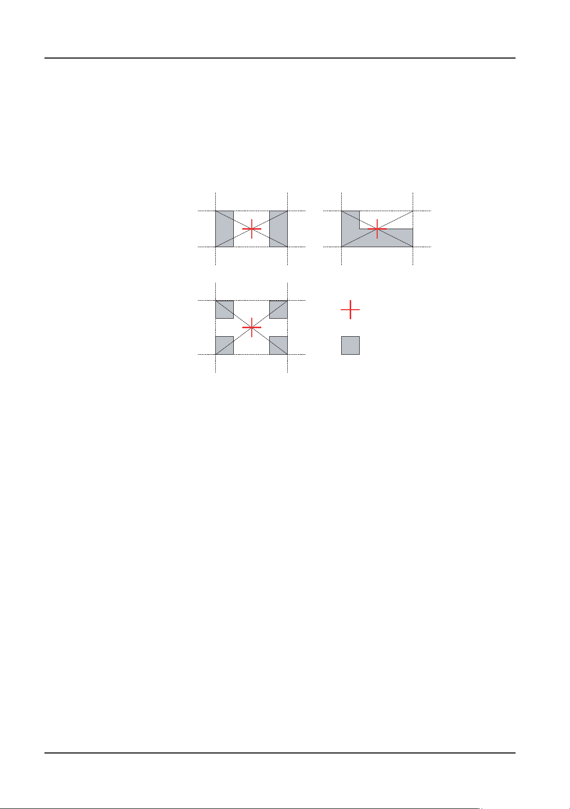
Mark center
Land pattern
01PRG-0001E