FUJI NXT Programming Manual QD004-18.pdf - 第97页
QD004-18 4. Part Data Settings NXT Programming Manual 87 Result Specify the type of check which will be perfor med on the leads in the element. Normally, this is set to [Inspect]. The check items are described belo w. Qu…
4. Part Data Settings QD004-18
86 NXT Programming Manual
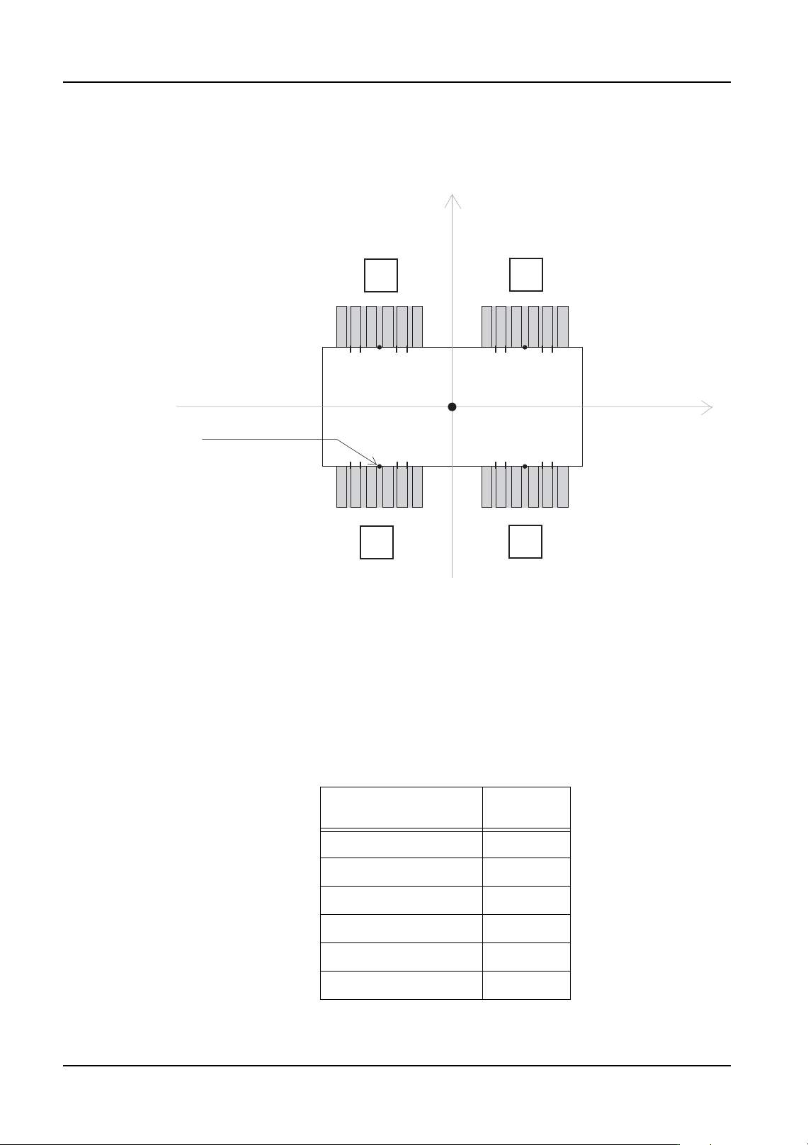
Position X, Y
This expresses the X- and Y-coordinates from the center of the part to the point on the side
of the part that is central with the element. (Refer to the figure below)
Side
Specify the side on which the element is located. Side numbers should always be assigned
as shown in the above figure (at direction 0).
P_pattern
Specify how the leads appear to the vision processing system. Select the P Pattern from
the choices that matches the lead image.
Refer to section 4.5 "P_pattern Details" for details on settings for this item. The table below
lists the common P_pattern settings for the NXT.
(Position X, Position Y)
(0, 0)
Body
Lead element group
1
4
3
2
Side 0
Side 1
Side 2
Side 3
NXTPRG007Eb
Part Type P Pattern
Number
SOIC, SOT 4
QFP (leads on 4 sides) 14
SOJ 4
PLCC 12
BGA (White body) 1
BGA (Black body) 2
QD004-18 4. Part Data Settings
NXT Programming Manual 87
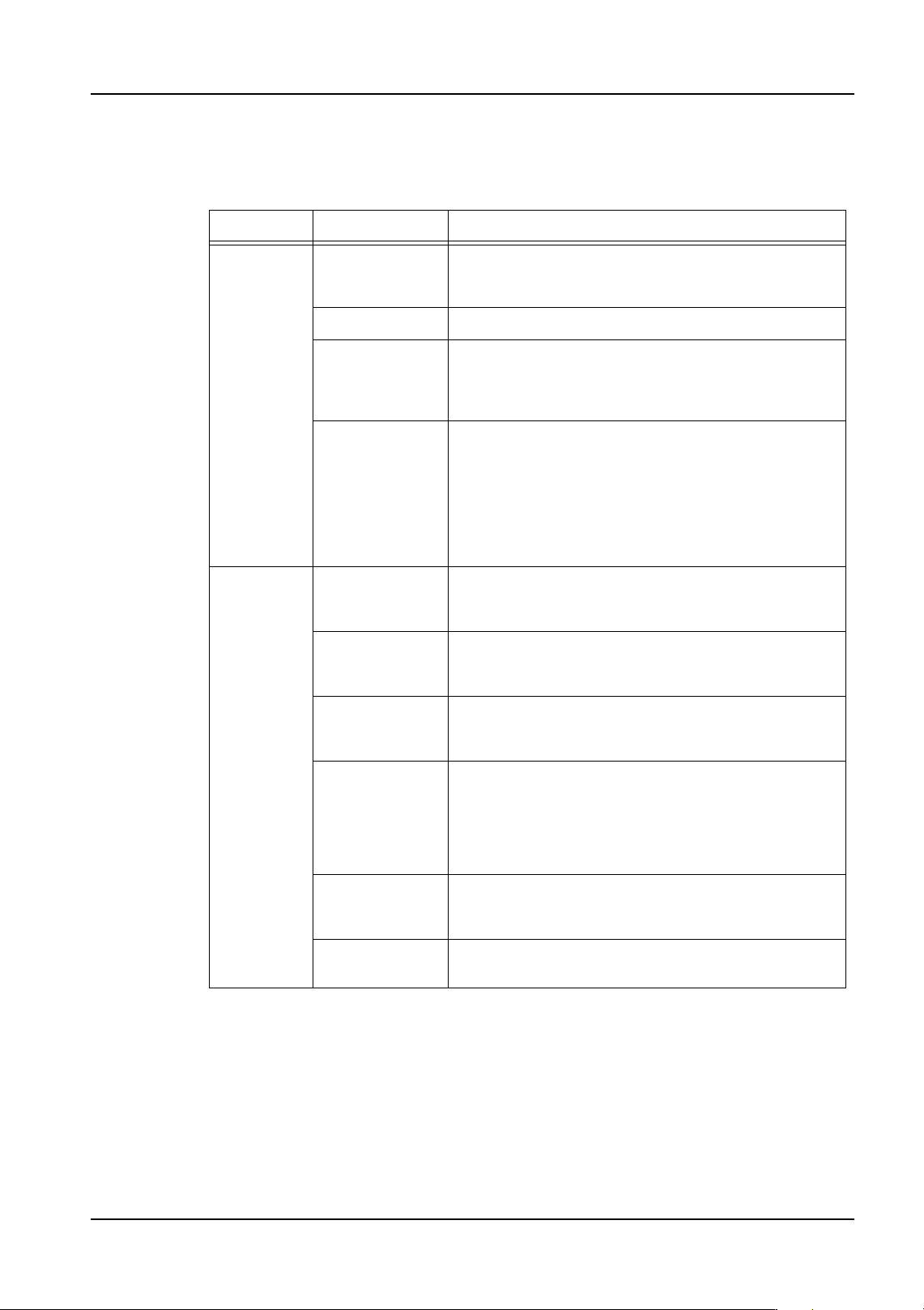
Result
Specify the type of check which will be performed on the leads in the element. Normally,
this is set to [Inspect]. The check items are described below.
Quantity
Specify the number of leads in the element.
Pitch
Specify the pitch of the element leads.
Width
Specify the width of element leads.
Group Setting Description
Vision
Processing
Options
Inspect Specifies the usual vision processing inspection
without special checks. This setting is specified for
standard parts which do not have special shapes.
Don't inspect The element is not inspected.
Virtual lead This setting is used to define virtual leads. When the
part is inspected, the vision processing system
verifies that there are no leads in the virtual lead area.
This function is useful for polarity checks.
Matrix Use this for BGAs and flip chips. Because the leads
are defined as a two dimensional array on these
parts, two records are necessary to define one
element. Result is set to “Inspect” in the first element
and in the second element result is set to "Matrix."
The "Matrix" setting alerts the vision processing
system that this is a grid-type part and that two
consecutive element records describe one element.
Check
Items
No length
tolerance check
Select this item to disable the lead length tolerance
check. This setting is used when there is a wide
variation in the length of the leads.
No width
tolerance check
Select this item to disable the lead width tolerance
check. This setting is used when there is a wide
variation in the width of the leads.
First pin check Use this to check that there is no lead to the left of the
very first lead detected (leads are inspected from left
to right).
Last pin check Select this item to enable the last pin check function.
In left to right vision processing of leads, this function
verifies that there is no lead to the right of the last
detected lead. In top to bottom vision processing of
leads, it verifies that there is no lead below the last
detected lead.
No center
length tolerance
check
Not supported
No center width
tolerance check
Not supported
4. Part Data Settings QD004-18
88 NXT Programming Manual
Width Tolerance
Specify the width tolerance of element leads.
Length
Specify the length of the element leads.
Length Tolerance
Specify the length tolerance of the element leads.
Center Tolerance
Specify the bend tolerance for the element leads.
4.3.4 Shape Process details
Body
Location Pin Length
Specify the length in mm of any locating pins on the shape if they are present. This setting
is especially required if using the insertion pressure function.
Part Pattern Tolerance X
This item is enabled for when Vision Type 240 to 242 is set in VPDplus. Check the help file
in VPDplus for more details.
Part Pattern Tolerance Y
This item is enabled for when Vision Type 240 to 242 is set in VPDplus. Check the help file
in VPDplus for more details.
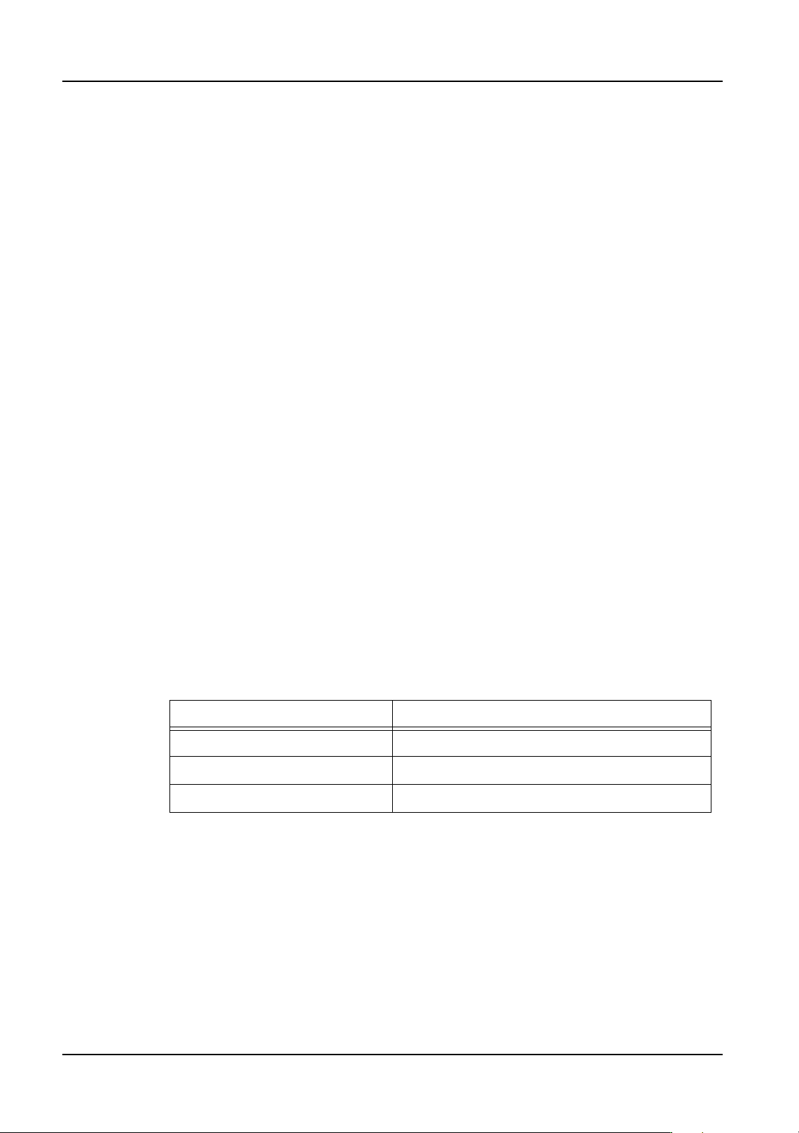
Lead
Check Point
Specify the point on the leads (measured from the end of the lead) that is checked. If 0 is
specified, the check occurs at the lead's 30% position. The following settings represent
general guidelines for various parts.
Quantity Check Limit
Specify the number of leads on leaded parts which must be detected for the part to pass
inspection. If this is set to 100%, all the leads must be detected. If set to 90%, 90% of the
leads must be detected. This is normally set to 100%.
Lead Brightness
This sets the brightness level for leads (bumps) that is used when automatic determination
of lead brightness is difficult. Correspondingly larger values should be specified for brighter
leads. When set to 0, brightness is determined automatically.
Part Type Setting
SOP / QPF 10 to 90% (standard setting: 30%)
PLCCs / SOJ 50 to 70% (standard setting: 60%)
BGA / Flip Chip 50%