FUJI NXT Programming Manual QD004-18.pdf - 第148页
4. Part Data Settings QD004-18 138 NXT Programming Manual Figure 5 Parts that have leads in the white body area. NXTVPP028Ea Figure 6 Poor lead shape (The leads are too short) Including parts with leads that have poor le…
QD004-18 4. Part Data Settings
NXT Programming Manual 137
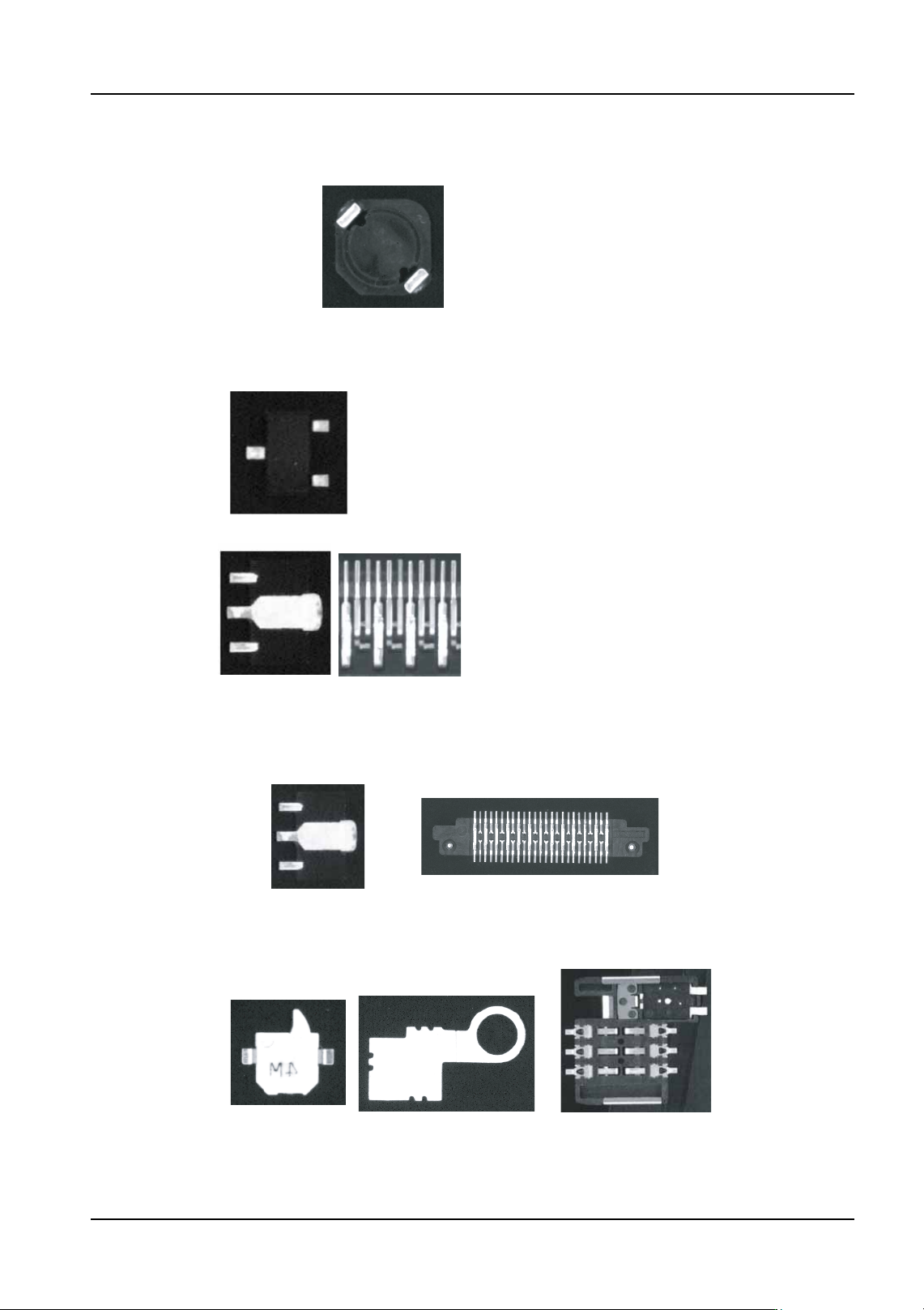
Figures 1 to 12
Figure 1 Example part with just 2 diagonal leads (inductor)
NXTVPP024Ea
Figure 2
Example part with rectangular and not connected to other leads (Vision Type 180)
Example parts with non-rectangular leads or are connected to some other leads (Vision Type 70)
NXTVPP025Ea
When the lead shape and the element shape do not
match, use vision type 70 or 18.
The element data shape and lead shapes match for the
minimold above. However, for the power transformer,
the center single lead must have element data definied
for side 0 and side 2.
It is the same for visible metal items even if they are not
connected to actual leads.
Figure 3
Example part with rectangular white reflective items (use vision type 70)
When distinguishing these areas is difficult, use vision type 18.
NXTVPP026Ea
Figure 4
Example parts when the outside shape of the white items is not rectangular
(vision type 18 usage examples)
NXTVPP027Ea
Use vision type 18 when distiniguishing is difficult.
4. Part Data Settings QD004-18
138 NXT Programming Manual
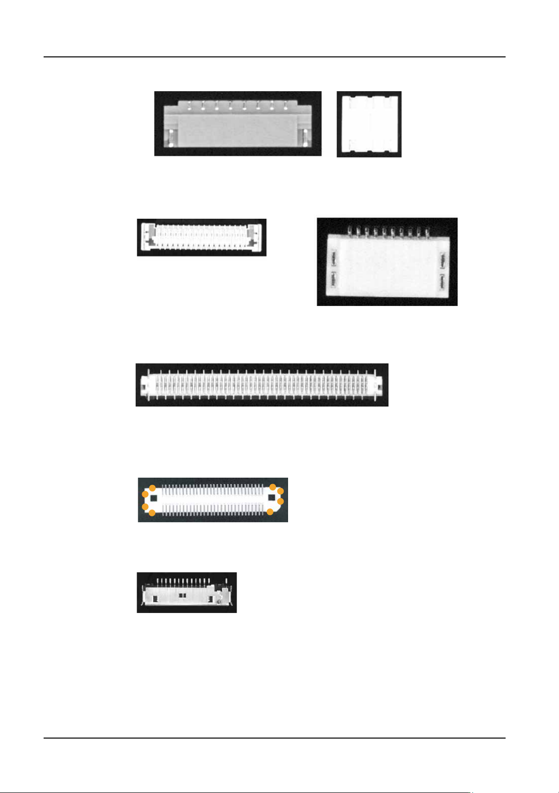
Figure 5 Parts that have leads in the white body area.
NXTVPP028Ea
Figure 6
Poor lead shape (The leads are too short) Including parts with leads that have
poor lead image definition.
NXTVPP029E
Figure 7
Example part with no more than 1 mm of body edge with no leads
or other items
NXTVPP030Ea
Figure 8
There should be at least one side with 2 body detection points, or there should be
at least two sides with one body detection point each.
(This part has 4 sides with 2 detection points each.)
NXTVPP031Ea
Figure 9
Example part with leads not connected to the white areas
To determine whether or not the leads and white area are
connected, observe the part and imagine how the lead will
be seen by the parts camera. Refer to the picture on the left.
The gull-wing leads made shadows around the lead bases.
We see the leads and white area as being separated. The
gold leads are bright and easily seen. The gull wing angle or
lead width makes the lead base appear dark. If VPDPlus and
the camera stand are available, use that to acquire an image
of the part. That is the easiest way to see how the machine
will see the part.
NXTVPP032Ea
QD004-18 4. Part Data Settings
NXT Programming Manual 139
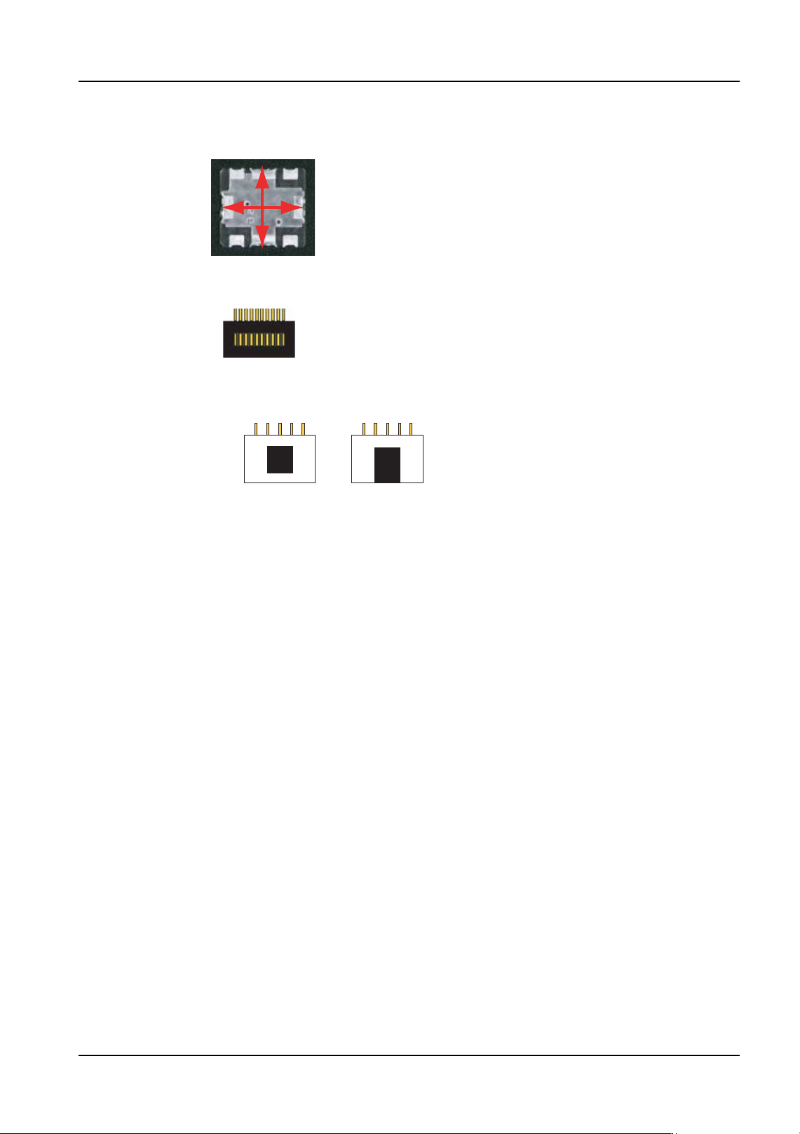
Figure 10
Example of a part with the white area size nearly
the same as the body size.
The size, not the area.
NXTVPP033Ea
Figure 11
Example part with lead-like shapes in the body of the part.
NXTVPP034Ea
Figure 12
Example of when the black area is surrounded
by white body and example when it is not.
NXTVPP035Ea