FUJI NXT Programming Manual QD004-18.pdf - 第106页
4. Part Data Settings QD004-18 96 NXT Programming Manual Process - Pin Check Pin Check Mode Specify the t ype of check to be per formed to che ck the direc tion of the part. The checks “Bottom Mark” and “Bump” are suppor…
QD004-18 4. Part Data Settings
NXT Programming Manual 95
Process - Vision
Vision Type
Refer to section Åu4.6Vision Type DetailsÅv for details on settings for this item.
Multi Camera
Specify the possible camera type(s) for the part. When no camera for the NXT is specified,
then any camera that can be used for the specified part data settings is used. If a camera(s)
is specified, then only that camera(s) can be used.
Vision Height Offset
This option is enabled when the side light camera is used in image acquisition. The use of
this option allows the image to be acquired with light hitting pin tip positions rather than the
bottom surface of the part.
Vision Area Offset X
This option is enabled for odd-form parts (when "240" to "243" is set in Vision Type and
image acquisition is performed). If the lead(s) of an odd-form part is protruding beyond the
image acquisition range, the range within which the image is acquired can be moved.
Vision Area Offset Y
This option is enabled for odd-form parts (when "240" to "243" is set in Vision Type and
image acquisition is performed). If the lead(s) of an odd-form part is protruding beyond the
image acquisition range, the range within which the image is acquired can be moved.
Exposure Time (VPDplus)
Displays the exposure time (msec) that is specified in VPDplus. If "0" is displayed, then the
exposure time is automatic based on the vision type. This setting can only be changed in
VPDplus.
Lighting Pattern (VPDplus)
Displays the lighting pattern that is specified in VPDplus. If "0" is displayed, then the lighting
pattern time is automatic based on the vision type for NXT and AIM machines. This setting
can only be changed in VPDplus. This setting is not used for machines other than NXT and
AIM.
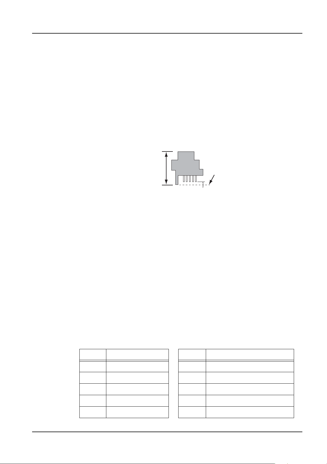
Body Height
01PRG065E
Part Body
Vision Height
+
-
Insertion pins
Setting Lighting Pattern Setting Lighting Pattern
0 Auto selected 16 Backlight
1 Sidelight 17 Backlight and sidelight
8 Incident 24 Backlight and incident
12 Incident and sidelight 30 Backlight, incident and sidelight
15 Frontlight all ON 31 Backlight and frontlight all ON
4. Part Data Settings QD004-18
96 NXT Programming Manual
Process - Pin Check
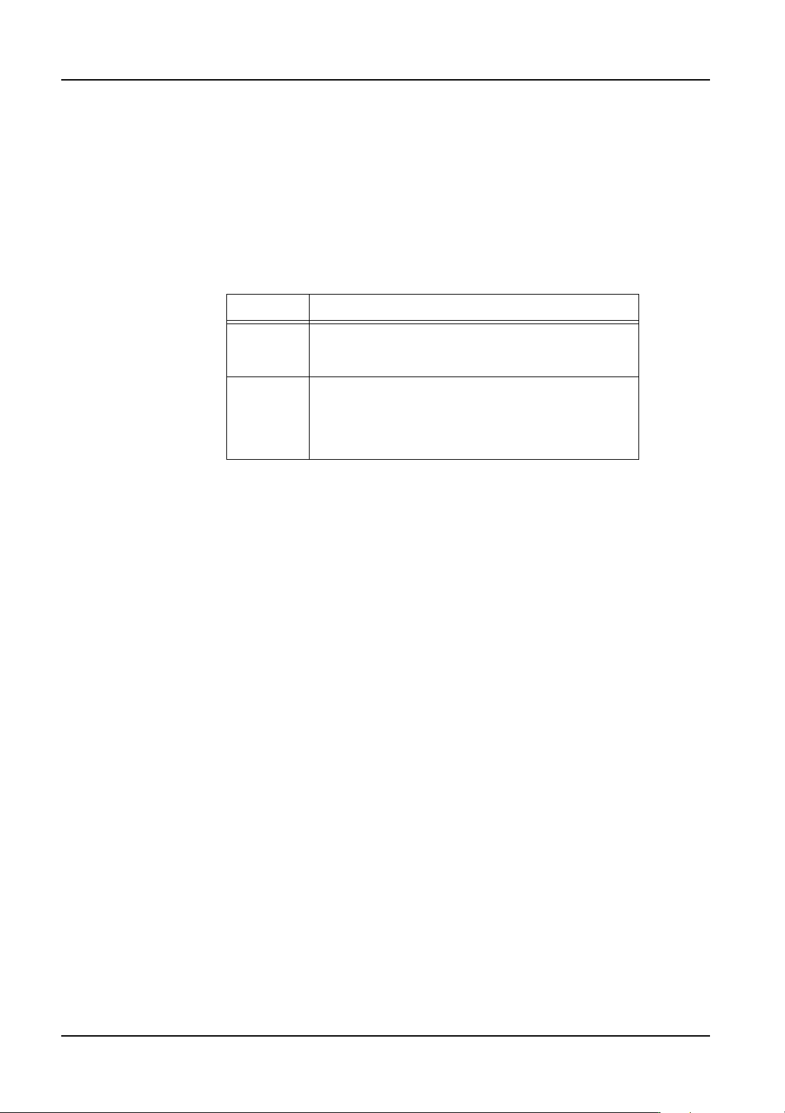
Pin Check Mode
Specify the type of check to be performed to check the direction of the part. The checks
“Bottom Mark” and “Bump” are supported on the NXT. If a mode other than those two are
specified, then the NXT ignores the pin check modes settings and a direction check is not
performed. If the part matches the specified conditions, then the part direction is
considered to be correct and normal vision processing is performed. If the part does not
match the specified conditions, then the direction is considered to be incorrect and an error
occurs.
Is Bottom Mark Present
This setting only displays if “Bottom Mark” is specified for the pin check. Specify whether
or not a bottom mark should be present in the specified area for orientation to be judged as
being correct.
Is Bump Present
This setting only displays if “Bump” is specified for the pin check. Specify whether or not a
bump should be present in the specified area for orientation to be judged as being correct.
Upper Left X
Specify the upper left X-coordinate of the check range in millimeters. The reference point
is the center of the body with the part oriented in the zero direction.
Upper Left Y
Specify the upper left Y-coordinate of the check range in millimeters. The reference point
is the center of the body with the part oriented in the zero direction.
Lower Right X
Specify the lower right X-coordinate of the check range in millimeters. The reference point
is the center of the body with the part oriented in the zero direction.
Lower Right Y
Specify the lower right Y-coordinate of the check range in millimeters. The reference point
is the center of the body with the part oriented in the zero direction.
Setting Description
Bottom
Mark
This is used to check for the presence or absence of
a mark on the bottom of a part in a specified location.
This check can be performed for all vision types.
Bump This is used to check for the presence or absence of
a bump (ball lead) on the bottom of a part in a
specified location. This check can only be
performed for vision types that are for parts with
bumps.

QD004-18 4. Part Data Settings
NXT Programming Manual 97
Process - Coplanarity
Do Coplanarity
Specify whether a coplanarity check is made with the optional coplanarity unit. Refer to the
coplanarity manual for information on the settings in this section.
Coplanarity Editor
Click to start the Coplanarity Editor for making coplanarity data for the optional coplanarity
unit. Refer to the coplanarity manual for more information.
Process - Flux
Do Flux
Specify whether or not flux is to be applied.
Dwell Time
Specify the length of time (sec) for the Z-axis to stay at the bottom of its travel to keep a part
dipped in flux.
Slow Dipping Height
Specify the height at which the Z-axis starts decelerating on its descent to the flux and ends
accelerating on its ascent from the flux.
Slow Dipping Down Speed
Specify the speed (%) after deceleration of the Z-axis during flux application. However, if
the machine has a [Slow Dipping Speed] setting specified, then that setting is used.
Slow Dipping Up Speed
Specify the speed (%) before acceleration of the Z-axis rising during flux application.
However, if the machine has a [Slow Dipping Speed] setting specified, then that setting is
used.
Squeegee Height
The film thickness during flux application for each part can be changed by specifying the
squeegee height. Set the squeegee height to the required film thickness amount.
Do Dipping Check
Specify whether or not to inspect for dropped parts when dipping parts in flux.
Process - Solder Paste
Do Check
Specify whether to check the application status of the solder paste. (Currently, only bump
related items are checked.)
High Brightness
Specify the maximum brightness of the bumps.
Low Brightness
Specify the minimum brightness of the bumps