FUJI NXT Programming Manual QD004-18.pdf - 第117页
QD004-18 4. Part Data Settings NXT Programming Manual 107 P_pattern 11, 12 These are used for parts with leads that are atta ched to the body at both ends of the leads and whose lead detect ion is not stable . The lea d …
4. Part Data Settings QD004-18
106 NXT Programming Manual
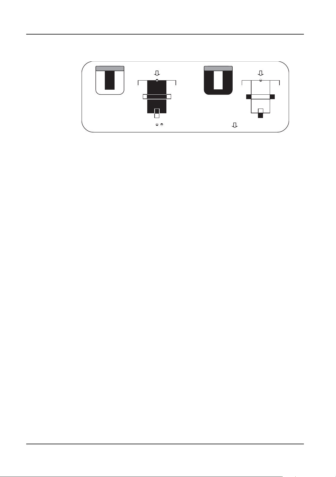
P_pattern 5, 6
The leads point towards the inside of the body of the part (opposite from types 3 and 4) and
are attached to the body at the base of the lead. Due to this, the base cannot be checked
with a caliper. The lead tips and widths are checked and the results are used to determine
the part positioning.
• Type 5: The lead appears black and the outside circumference is white.
• Type 6: The lead appears white and the outside circumference is black.
These are primarily used for parts with leads on one side or two opposing sides.
With parts that have leads on two perpendicular sides or more, the lead width direction is
only required for determining the positioning, therefore it is recommended to select a
different p_pattern (type: 11, 12, 15, 16) that matches the processing conditions.
Example Target Parts
Type 5: PLCC socket parts processed with backlighting.
Type 6: Parts with leads pointing towards inside of the body and has a black background
and body and is processed with frontlighting.
NXTVPP015E
:Entered element position
:Defined element direction
Type 6 Type 5
QD004-18 4. Part Data Settings
NXT Programming Manual 107
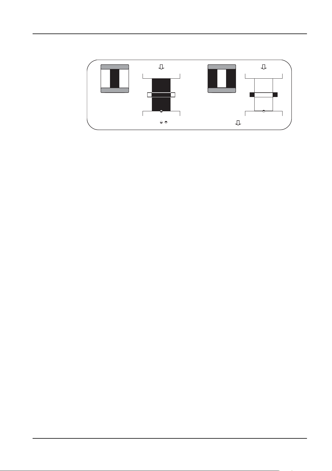
P_pattern 11, 12
These are used for parts with leads that are attached to the body at both ends of the leads
and whose lead detection is not stable. The lead widths are checked and the results are
used to determine the part positioning.
• Type 11: The lead appears black and the outside circumference is white.
• Type 12: The lead appears white and the outside circumference is black.
Except for parts using vision type 151 and picked up by a mechanical chuck in the Y-
direction, these p_patterns can only be used for parts that have leads on two perpendicular
sides or more. However, if it is possible to detect either end of the lead in a stable manner,
it is recommended to select a different p_pattern (type: 13, 14, 15, 16) that matches the
processing conditions.
Furthermore, the information for the part positioning using the lead length is not acquired
so these types cannot be used for parts with leads on one side or two opposing sides only.
Example Target Parts
Type 11: TAB parts processed with backlighting.
Type 12: Parts with lead tips that poorly reflect using vision type 151 and a mechanical
chuck to pick the part in the Y-direction processed with frontlighting.
NXTVPP016E
:Entered element position
:Defined element direction
Type 11 Type 12
4. Part Data Settings QD004-18
108 NXT Programming Manual
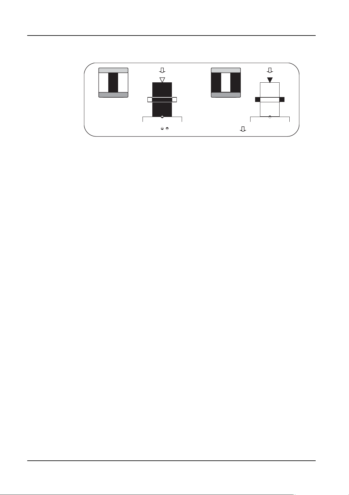
P_pattern 13, 14
Basically, these are the same as p_pattern types 3 and 4. The major difference is that with
these p_patterns, the outward pointing lead tip is not used for determining the part
positioning. The lead width detection results only are used to determine the part
positioning. The lead tip detection results are used only as reference data for internal vision
processing items.
• Type 13: The lead appears black and the outside circumference is white.
• Type 14: The lead appears white and the outside circumference is black.
It is only possible to use this for parts that have leads that are to be detected on two
perpendicular sides or more.
Furthermore, the information for the part positioning using the lead length is not acquired
so these types cannot be used for parts with leads on one side or two opposing sides only.
Example Target Parts
Type 13: QFP parts processed with backlighting.
Type 14: Black background and body parts (e.g., QFP) processed with frontlighting.
NXTVPP017E
:Entered element position
:Defined element direction
Type 13 Type 14