XP Type II 工程师培训手册 (2.0).pdf.pdf - 第105页
FK-9F98-34 XP T ype II Series T raining T ext for Service Engineers Edition 2.0 XP242E – Chapter 1 Initial Adjustment Page 1 of 8 Chapter 1 – Initial adjustment 1.1 Leveling 1. Measuring equipment: track level (0.02/1000…

C
C
h
h
a
a
p
p
t
t
e
e
r
r
1
1
I
I
n
n
i
i
t
t
i
i
a
a
l
l
A
A
d
d
j
j
u
u
s
s
t
t
m
m
e
e
n
n
t
t

FK-9F98-34 XP Type II Series Training Text for Service Engineers
Edition 2.0 XP242E – Chapter 1 Initial Adjustment Page 1 of 8
Chapter 1 – Initial adjustment
1.1 Leveling
1. Measuring equipment: track level (0.02/1000mm)
2. Before leveling carry out the following procedure:
3. On new machines remove the red bracket that secures the X and Y axes during transit.
4. Remove the IN and OUT side conveyor covers.
5. Remove the mesh-cover that surrounds the MTU empty tray eject area at the rear of the
machine.
6. Check that the accessory parts are present. On a standard machine there should be:
4 back-up pins (Solid type)
1 Coupler for the air supply
1 Waste tape box
1 Lock
1 MFU
7. Remove the waste tape duct.
8. Check that the cooling fan is not blocked.
Machine Leveling
1. Set two track levels on the machine at (position
A) and carry out initial leveling using leveling
bolts 1 to 4 shown in the diagram.
2
4 3
1
B
A
2. After initial leveling is complete, set the track levels at
(position B) and confirm the machine is level. The track
levels should indicate that the machine is level at both
points A and B. If it proves impossible to level within
tolerance please contact FUJI.
3. After completing initial leveling, place leveling sheets at
the remaining points and lock the nuts for all of the
leveling bolts.
Tolerance 0.10mm/1000mm
Fuji Machine Mfg. Co., Ltd. Okazaki.
SMT Equipment Quality Assurance Dept.
1 – 1 CS Section
FK-9F98-34 XP Type II Series Training Text for Service Engineers
Edition 2.0 XP242E – Chapter 1 Initial Adjustment Page 2 of 8
4. Finally confirm that all of the leveling sheets are stable,
and check once again that the leveling is within
tolerance.
1.2 Power and Air Connection
Power Supply Connection
L2 L3 L1
1. Open the power supply BOX at the lower right hand
side of the machine and pull the power line through the
bottom of the BOX.
Red
2. Connect the ground terminal and the ground wire first.
3. Connect the three wires of the power supply cable to
the three breaker box (KG41B) terminals.
L1: red L2: white L3: black
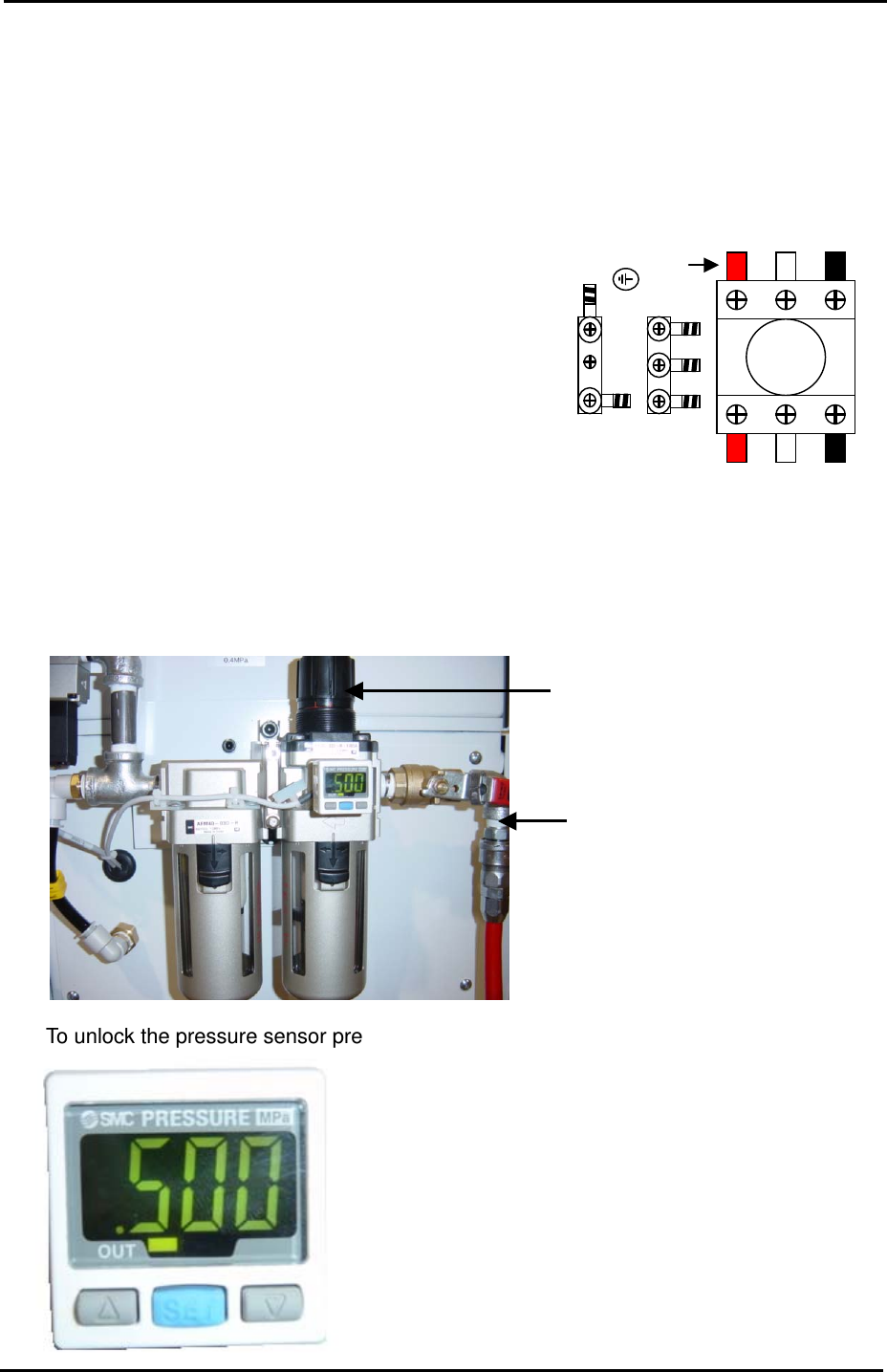
Air Pressure Setting
1. Connect the hose to the air inlet at the machine rear side.
Air Regulator
Air Inlet
2. To unlock the pressure sensor press [SET] for more than 4 seconds.
Pressure Sensor
Fuji Machine Mfg. Co., Ltd. Okazaki.
SMT Equipment Quality Assurance Dept.
1 – 2 CS Section