XP Type II 工程师培训手册 (2.0).pdf.pdf - 第209页
FK-9F98-34 XP Series T ype II T raining T ext for Service Engineers Edition 2.0 XP242E – Chapter 8 T ype II MTU Adjustment Page 16 of 18 5. Manually move the X, Y and Z axes until the no zzle jig can slide smoothly into …
FK-9F98-34 XP Series Type II Training Text for Service Engineers
Edition 2.0 XP242E – Chapter 8 Type II MTU Adjustment Page 15 of 18
8.20 Tray Detection Sensor Adjustment
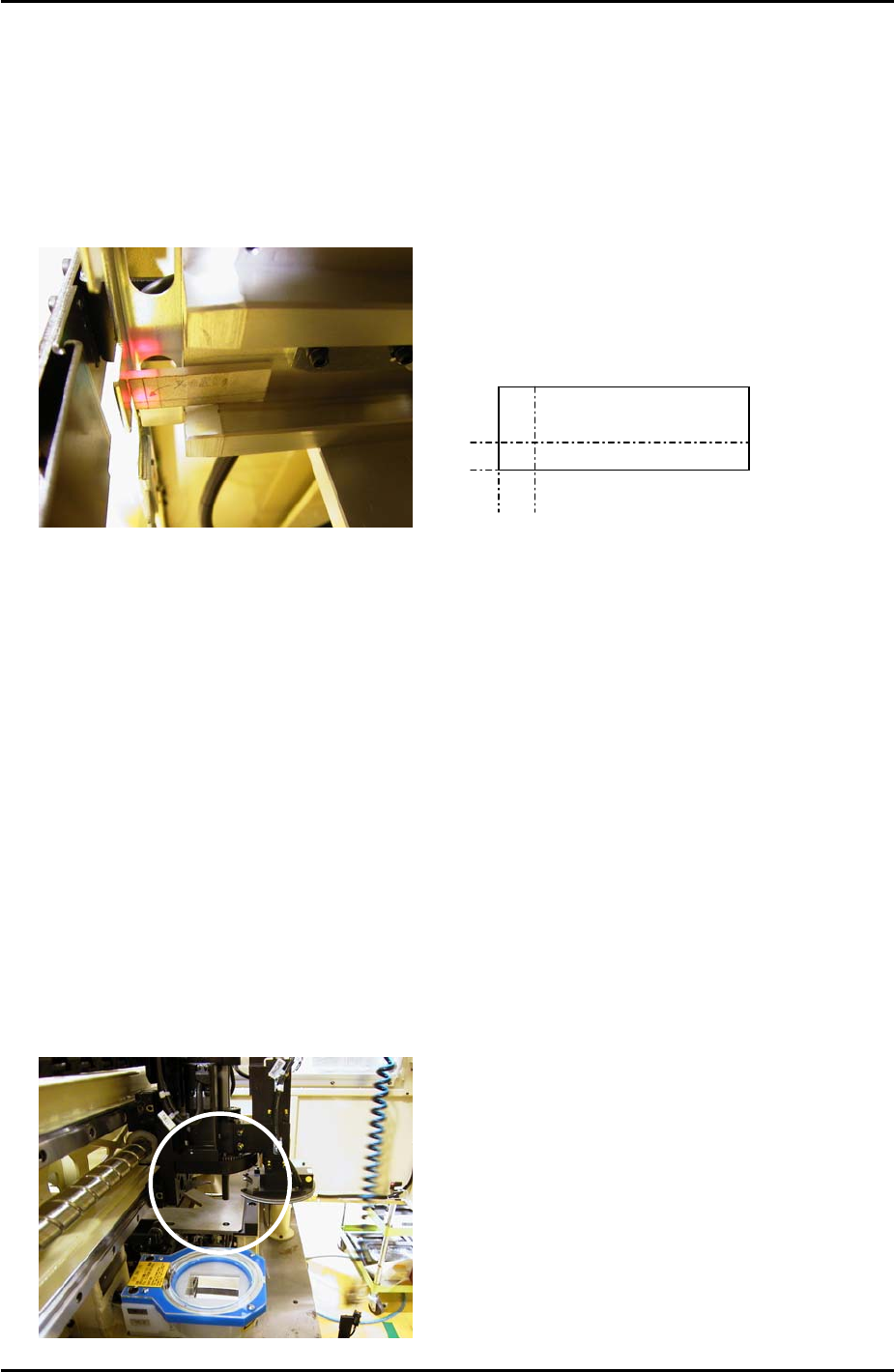
1. Move the T-axis to the “T_TrayOrg” position.
2. Set the tray shutter at position 1.
3. Slide the acrylic jig along the slot [01,02] magazine rail until it contacts the shutter as
shown below:
Acrylic Jig
4mm
5mm
4. Adjust the position of the tray detection sensor so that the sensor beam is in the center of
the cross on the jig.
5. If it is impossible to set the sensor beam in the center of the cross then set it as close as
possible.
8.21 Tray Pickup Position Measurement
1. Set the tray jig (Z9531DEPJ3522) in slot [01,02] and select [Manual Operation] – [Tray
Operation] – [01,02] – [Move Elevator] to bring the jig to the tray origin position.
2. Select [Advance Shuttle] to bring the tray jig to the tray pickup position.
3. Select [Maintenance A] – [I/O Check] – [Y021 NozzleUnhold] – [OFF] and attach the tray
pickup position nozzle jig (Z9731DEPJ3650) to the placing head.
4. Bring the placing head over the tray jig and then press the emergency stop button to cut
the 200V power supply to the servos:
Fuji Machine Mfg. Co., Ltd. Okazaki
SMT Equipment Quality Assurance Dept.
8 – 15 CS Section

FK-9F98-34 XP Series Type II Training Text for Service Engineers
Edition 2.0 XP242E – Chapter 8 Type II MTU Adjustment Page 16 of 18
5. Manually move the X, Y and Z axes until the nozzle jig can slide smoothly into the tray
pick up position jig hole:
6. Select [Maintenance C] – [Proper Data Editor] – [Machine Origin] –
[X_stage2Org/Y_stage2Org] – [Direct Servo Input] to save the current X and Y-axes
positions in proper data.
7. To set the [Z_stage2surface] proper data remove the tray jig (Z9531DEPJ3522). Set a
standard tray pallet in slot [01,02] and select [Manual Operation] – [Tray Operation] –
[01,02] – [Move Elevator] to bring the tray pallet to the tray origin position.
8. Select [Advance Shuttle] to bring the tray pallet to the tray pickup position.
9. Replace the pickup position nozzle jig (Z9731DEPJ3650) with the standard nozzle jig
(Z9531DEPJ0070).
10. Bring the placing head over the tray pallet and then press the emergency stop button to
cut the 200V power supply to the servos.
11. Manually descend the Z-axis until the nozzle jig just contacts the surface of the tray
pallet.
12. Select [Maintenance C] – [Proper Data Editor] – [Machine Origin] – [Z_stage2surface] –
[Direct Servo Input] to save the current Z-axis position in proper data.
8.22 Returning Proper Data
1. Select [Maintenance C] – [Proper Data Editor] – [Operation] – [TrayDetectMotion] and
change from 0 to 2.
2. Select [OPERATION_2] – [JogInterlockOFF] and change from 1 to 0.
8.23 Re-Tightening Check
1. Carry out a re-tightening check for any bolts that were tightened during the adjustment.
Fuji Machine Mfg. Co., Ltd. Okazaki
SMT Equipment Quality Assurance Dept.
8 – 16 CS Section

FK-9F98-34 XP Series Type II Training Text for Service Engineers
Edition 2.0 XP242E – Chapter 8 Type II MTU Adjustment Page 17 of 18
8.24 Final Check
1. Confirm that bypass keys, jigs, wrenches, and other foreign objects do not remain in the
machine.
8.25 Backing Up
1. Back up the system files at [Maintenance B] – [Backup].
Fuji Machine Mfg. Co., Ltd. Okazaki
SMT Equipment Quality Assurance Dept.
8 – 17 CS Section