XP Type II 工程师培训手册 (2.0).pdf.pdf - 第206页
FK-9F98-34 XP Series T ype II T raining T ext for Service Engineers Edition 2.0 XP242E – Chapter 8 T ype II MTU Adjustment Page 13 of 18 Measured V alue Offset V alue + 0.04mm 0.00 + 0.03mm 0.01 + 0.05mm -0.01 6. Repeat …
FK-9F98-34 XP Series Type II Training Text for Service Engineers
Edition 2.0 XP242E – Chapter 8 Type II MTU Adjustment Page 12 of 18
flashes].
10. Block the sensor and press the dial switch once. A number displays on the Digital
Display. Confirm that this number is greater than 10.
11. Press the dial switch once [SET in the Mode Display flashes and “2P” is displayed on the
Digital Display].
12. Turn the dial switch until RUN flashes in the Mode Display and “AA” is displayed on the
Digital Display.
13. Press the dial switch once [RUN in the Mode Display stops flashing and a number
appears in the Digital Display].
14. The sensor amplifier adjustment is now complete, confirm that the changeover switch is
set to “LO”.
15. Confirm the sensor operation by I/O. The I/O output X03C TraySetChk should be OFF
when the sensor is interrupted and ON when there is no interruption.
Sensor Condition Output
Interrupted OFF
Uninterrupted ON
8.17 Tray Pitch Offset Measurement
1. Select [Manual Operation] – [Tray Operation] – [Tray height measurement].
2. After tray height measurement is completed select slot [11,12] – [Move Elevator] to go to
the tray transference position for that slot.
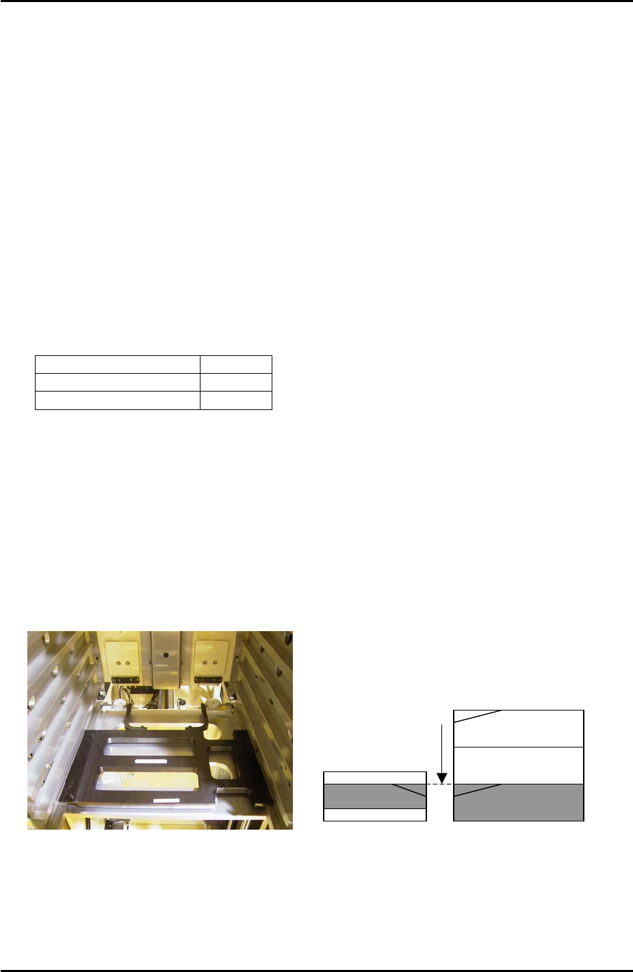
3. Measure the difference in height between the right hand of the slot and the U axis
conveyor rail. Use two dial gages and the jig shown in the photo (Z9731ADEPJ8131):
U axis
Measure height of the
magazine slots relative
to the U axis and input
offsets in proper data.
Magazine [41,42]
4. At this position the right hand magazine slot should be 0.04mm higher than the U axis
conveyor rail. If this is not the case it is necessary to input an offset.
5. Select [Maintenance C] – [Proper Data Editor] – [Tray] – [_ElevatorOfst2] and input the
offset value as follows:
Fuji Machine Mfg. Co., Ltd. Okazaki
SMT Equipment Quality Assurance Dept.
8 – 12 CS Section
FK-9F98-34 XP Series Type II Training Text for Service Engineers
Edition 2.0 XP242E – Chapter 8 Type II MTU Adjustment Page 13 of 18
Measured Value Offset Value
+ 0.04mm 0.00
+ 0.03mm 0.01
+ 0.05mm -0.01
6. Repeat for all remaining slots:
Slot Offset
[11,12] _ElevatorOfst2
[21,22] _ElevatorOfst3
[31,32] _ElevatorOfst4
[41,42] _ElevatorOfst5
[51,52] _ElevatorOfst6
[61,62] _ElevatorOfst7
[71,72] _ElevatorOfst8
[81,82] _ElevatorOfst9
[91,92] _ElevatorOfst10
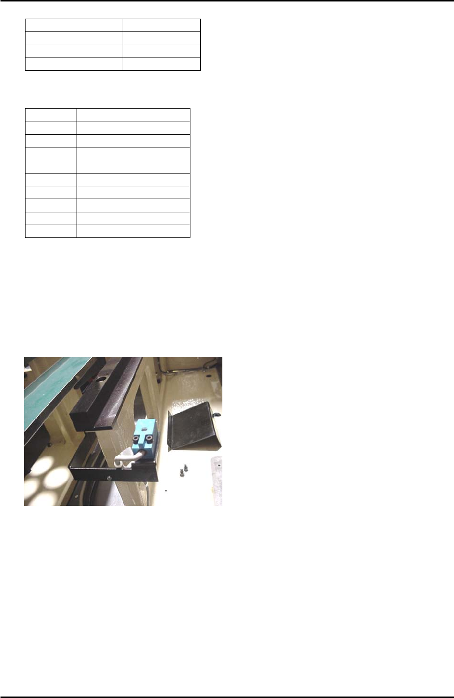
8.18 Tray Pickup Position Check Sensor Adjustment
1. Put a tray pallet in slot [01,02] and bring it to the tray transference position by selecting
[Manual Operation] – [Tray Operation] – [01,02] – [Move Elevator].
2. Select [Manual Operation] – [Tray Operation] – [Advance Shuttle] – to move the tray
pallet to its forward end.
3. At this position set the height of the tray pickup position check sensor so that there is a
gap of 2.5mm between the top surface of the sensor and the bottom surface of the tray
pallet.
4. Select [Maintenance A] – [I/O Check] – [X039 P.PosTrayDetect] to monitor the sensor
signal. When the sensor is interrupted the I/O is OFF, but the LED is ON.
5. Adjust the position of the sensor in the Y direction so that the LED just comes ON and
then fix it 3mm further in that direction.
6. Check the sensor operation by I/O.
Fuji Machine Mfg. Co., Ltd. Okazaki
SMT Equipment Quality Assurance Dept.
8 – 13 CS Section
FK-9F98-34 XP Series Type II Training Text for Service Engineers
Edition 2.0 XP242E – Chapter 8 Type II MTU Adjustment Page 14 of 18
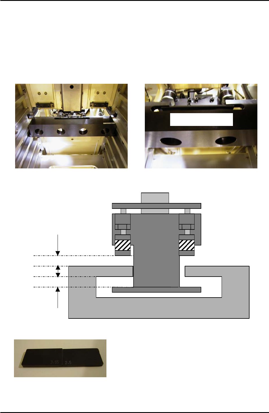
8.19 Shuttle Clamp Position Check
1. Temporarily set the large block jig (Z9631ADEPJ8172) in the center of slot [41,42].
2. Move the T-axis so that slot [51,52] moves to the tray transference position.
3. Position the large block jig so that the cut out section hooks over the shuttle clamper as
shown in the photographs below. Make sure that the large block jig is pushed as far
forward as possible so that it is right up against the MTU guide rails:
Z9631ADEPJ8172
4. Under these conditions check that the front and back clearances between the shuttle
clamper and jig are within tolerance as shown in the following diagram:
2.5mm to 3.55mm
2.5mm to 3.55mm
Z9631ADEPJ8172
5. Use a feeler gage jig or similar object to measure the gaps:
3.55 2.5
6. If the clearance is not within tolerance recheck the shuttle clamping position adjustment
(9.16) and the tray catch stopper adjustment (9.23).
Fuji Machine Mfg. Co., Ltd. Okazaki
SMT Equipment Quality Assurance Dept.
8 – 14 CS Section