XP Type II 工程师培训手册 (2.0).pdf.pdf - 第62页
FK-9F98-34 XP T ype II Series T raining T ext for Service Engineers Edition 2.0 XP142E – Chapter 6 Proper Dat a Measurement s Page 3 of 30 Aligning the Horizont al Cross Hair 1. Loosen the three bolts at taching the came…
FK-9F98-34 XP Type II Series Training Text for Service Engineers
Edition 2.0 XP142E – Chapter 6 Proper Data Measurements Page 2 of 30
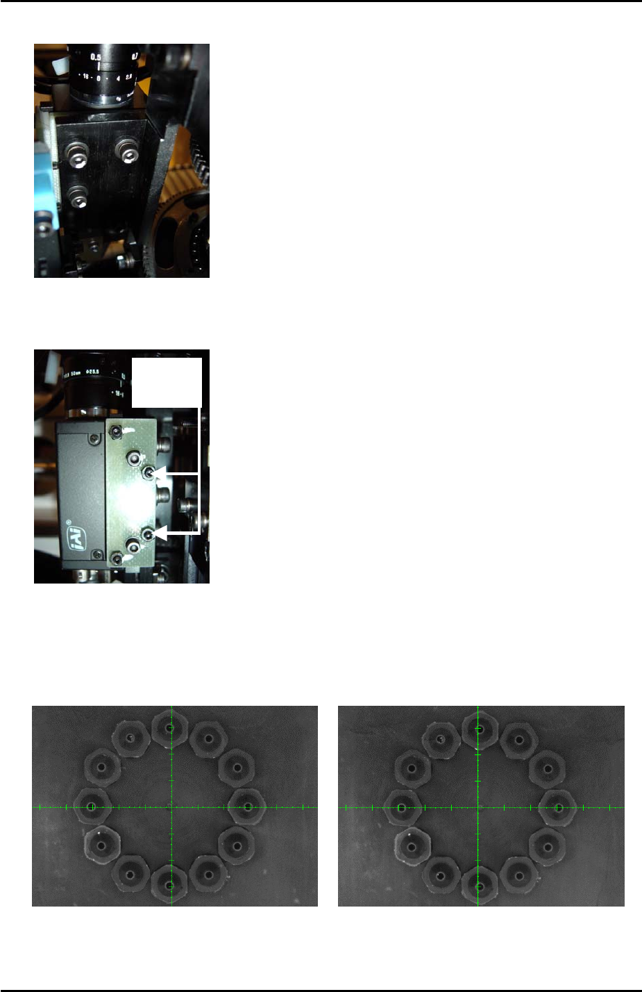
2. Loosen the 4 bolts on the back of the camera installation plate:
3
4
2
1
3. Unlock the nuts and use the two hollow bolts to adjust the tilt of the camera in the X
direction until the revolver center is aligned with the vertical cross hair:
Hollow
Bolts
4. Select the [Side2] camera and inch the revolver above the side 2 light source. Compare
the position of the vertical cross hair at side 1 and side 2. If the alignment is different
adjust so that the alignment is evened out between the two sides as illustrated in the
following example:
SIDE 2 SIDE 1
5. Finally lock the four bolts on the back of the camera installation bolt and the nuts for the
two hollow bolts.
Fuji Machine Mfg. Co., Ltd. Okazaki
SMT Equipment Quality Assurance Dept.
6 – 2 CS Section
FK-9F98-34 XP Type II Series Training Text for Service Engineers
Edition 2.0 XP142E – Chapter 6 Proper Data Measurements Page 3 of 30
Aligning the Horizontal Cross Hair
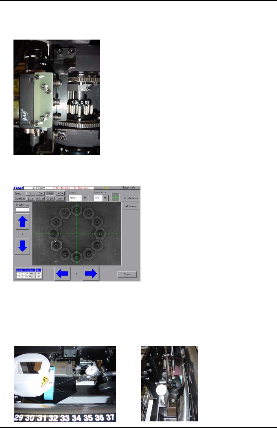
1. Loosen the three bolts attaching the camera installation bracket to the placing head:
3
1 2
2. Adjust the tilt of the camera in the Y direction until the revolver center is aligned with the
horizontal cross hair at side 1.
3. Select the [Side2] camera and inch the revolver above the side 2 light source. Compare
the position of the horizontal cross hair at side 1 and side 2. The alignment should be
basically the same. If, however, the alignment is considerably different, carry out the
following procedure:
4. Measure the flatness of the side 1 prism in the Y direction using a dial gage as shown in
the photos below:
Fuji Machine Mfg. Co., Ltd. Okazaki
SMT Equipment Quality Assurance Dept.
6 – 3 CS Section
FK-9F98-34 XP Type II Series Training Text for Service Engineers
Edition 2.0 XP142E – Chapter 6 Proper Data Measurements Page 4 of 30
5. The prism should be flat to within 0.01mm. If necessary adjust so that it is flat.
6. If the flatness of the side 1 prism has been adjusted, select the [Side1] camera and inch
the revolver above the center of the side 1 light source. Readjust the tilt of the camera in
the Y direction until the horizontal cross hair is aligned with the revolver center.
7. Select the [Side2] camera and inch the revolver above the center of the side 2 light
source. The horizontal cross hair should be aligned with the revolver center. If not align
the horizontal cross hair with the revolver center by adjusting the tilt of the side 2 prism.
8. Finally lock all bolts loosened during the adjustment.
6.3 Prism Position
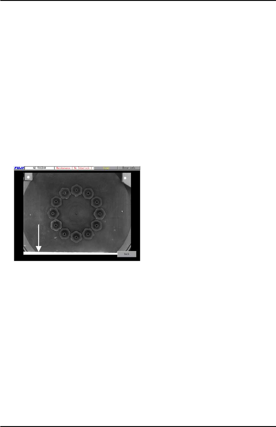
1. In [Maintenance Mode] inch the revolver above the center of the side 1 light source and
select the [Side1] camera to display the live image.
2. Press [Full Screen] and check the image on the monitor. In the following example the
light source is still visible at the bottom of the screen:
Light
Source
3. Inch the Y axis until the light source is no longer visible in the [Full Screen] image then
record the Y axis counter value at that position.
4. Select [Maintenance] – [Proper Data Editor] – [PRIZM POSITION] – [PrismFront] – and
input the counter value recorded in step 3.
5. Repeat the procedure for the side 2 prism position [PrismBack].
Fuji Machine Mfg. Co., Ltd. Okazaki
SMT Equipment Quality Assurance Dept.
6 – 4 CS Section