XP Type II 工程师培训手册 (2.0).pdf.pdf - 第161页
FK-9F98-34 XP T ype II Series T raining T ext for Service Engineers Edition 2.0 XP242E – Chapter 6 Proper Data Mea surement s Page 6 of 30 5. Select [X Unit measure] to measure the mark camera resolution. Note that this …
FK-9F98-34 XP Type II Series Training Text for Service Engineers
Edition 2.0 XP242E – Chapter 6 Proper Data Measurements Page 5 of 30
9. Answer NO to the question “Do you save calibration data to FD?”
10. To the next question “Save Calibration Data?” answer YES.
11. Confirm that the resolution results are within the tolerances shown below:
Mark camera resolution tolerance
X_Unit 0.0170 ~ 0.0189
X_View 10.9 ~ 12.1
Y_Unit 0.0170 ~ 0.0189
Y_View 8.16 ~ 9.07
12. The resolution calibration is now complete. Press [OK] to return to the
[Maintenance A] screen.
6.3 Mark Camera Orientation
1. Select [Maintenance A] – [JOG] – [Fiducial] and display the crosshairs on the
screen.
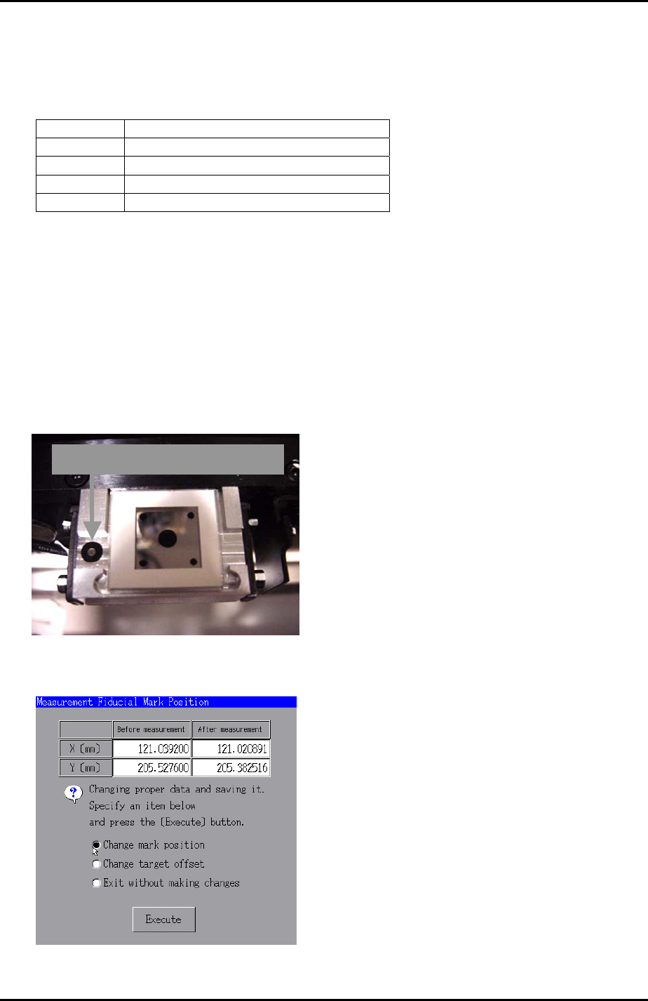
2. Inch the mark camera until it is centered on the fiducial mark on the left of the glass
gage station.
Glass gage station fiducial mark
3. Select [Maintenance C] – [Mark camera Measurement] – [FMarkPos Measure] –
[START] – [Change mark position] – [Execute] to save the fiducial mark position.
4. Select [Angle Measure] to measure the mark camera orientation.
Fuji Machine Mfg. Co., Ltd. Okazaki.
SMT Equipment Quality Assurance Dept.
6 – 5 CS Section
FK-9F98-34 XP Type II Series Training Text for Service Engineers
Edition 2.0 XP242E – Chapter 6 Proper Data Measurements Page 6 of 30
5. Select [X Unit measure] to measure the mark camera resolution. Note that this is
not the primary resolution measurement, therefore do not save the results. Check
that the resolution values are within 0.05mm of those recorded in step 6.2 and then
press cancel.
6. Select [Y Unit measure] to measure the mark camera resolution. Note that this is
not the primary resolution measurement therefore do not save the results. Check
that the resolution values are within 0.05mm of those recorded in step 6.2 and then
press cancel.
7. If the deviation between the resolution values recorded in steps 6.2 and 6.3 is more
than 0.05mm re-measure the resolution using the glass gage procedure described
in 6.2.
8. Note that 6.2 is the primary resolution measurement because it reads a whole
series of marks on the glass gage and takes into account lens distortion.
9. Should the values in 6.2 and 6.3 fail to match within the tolerance after re-
measurement, please contact FUJI.
6.4 Board Origin
1. Select [Maintenance A] – [I/O check] – [Y02A Main StationSt] – and raise the main
stopper.
2. Select [Maintenance A] – [JOG] – [Fiducial] and display the crosshairs on the
screen.
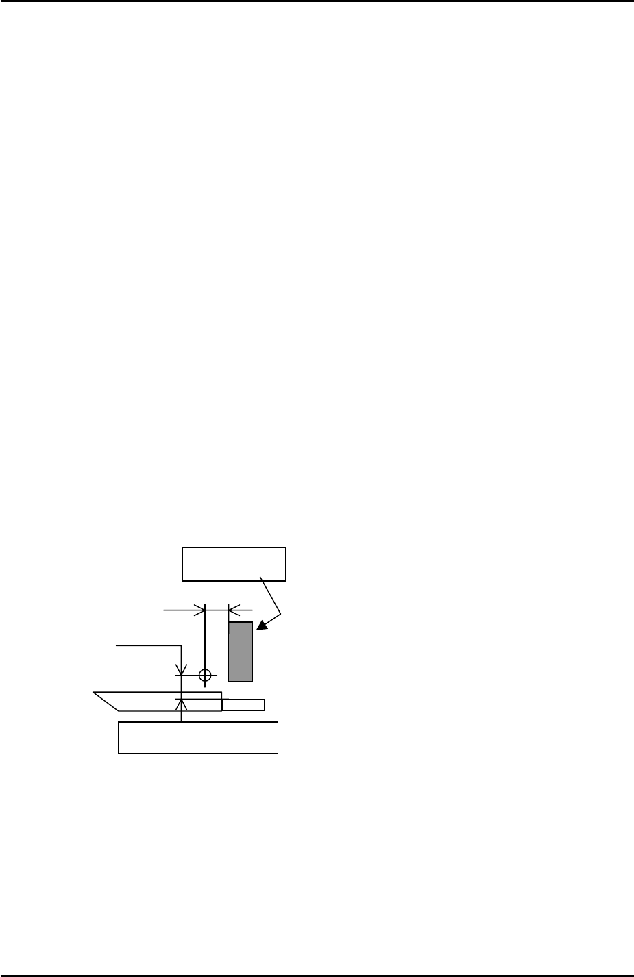
3. Set the vertical cross hair flush with the left side of the main stopper and then use
the inching tabs to move the X axis exactly 5mm in the minus direction.
5.0 mm
5.25 mm
Side of the reference rail
Main Stopper
4. Select [Maintenance C] – [Proper Data Editor] – [Machine Origin] – [X_board
Origin] and use direct servo input to save the current position to proper data.
5. Return to the [JOG] screen and set the horizontal cross hair flush with the side of
the reference rail and then use the inching tabs to move the Y axis 5.25mm in the
plus direction.
6. Select [Maintenance C] – [Proper Data Editor] – [Machine Origin] – [Y_board
Origin] and use direct servo input to save the current position to proper data.
Fuji Machine Mfg. Co., Ltd. Okazaki.
SMT Equipment Quality Assurance Dept.
6 – 6 CS Section
FK-9F98-34 XP Type II Series Training Text for Service Engineers
Edition 2.0 XP242E – Chapter 6 Proper Data Measurements Page 7 of 30
6.5 Measuring Z0
Jig: plate jig (AJPJ0060).
Jig: nozzle jig (Z9531DEPJ0070).
1. Select [Maintenance A] – [I/O check] – [Y021 Nozzle UnHold] – [OFF] and attach
the nozzle jig.
2. Clamp the plate jig in the main conveyor.
3. Bring the nozzle jig above the plate jig and then press the emergency stop button to
cut the 200 volt power supply to the servos.
4. Manually descend the Z-axis until the nozzle jig contacts the plate jig surface.
5. Select [Maintenance C] – [Proper data editor] – [Machine Origin] – [Z_board
surface] and use direct servo input to save the current position in proper data.
6.6 Parts Camera Center
Note: the adjustment procedure is the same for both the front and rear cameras.
Camera settings
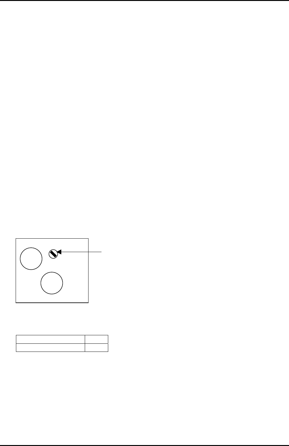
1. Set the parts camera aperture to 11 (this is half way between the 8 and the 16
setting marks).
DC IN/
SYNC
VIDEO
OUT
TRIGGER
GAIN
Gain volume adjustment
2. Select [Maintenance C] – [Proper Data Editor] – [MACHINE_TYPE] and check the
following proper data settings:
_xpTI1200A 1
_xpSetCVA1Cam 13
3. Ensure the lens unit attachment is fastened with adhesive (Loctite 425).
4. If attaching the camera unit to the camera installation bracket, tighten the bolts with
0.5Nm torque and apply adhesive.
Fuji Machine Mfg. Co., Ltd. Okazaki.
SMT Equipment Quality Assurance Dept.
6 – 7 CS Section