XP Type II 工程师培训手册 (2.0).pdf.pdf - 第171页
FK-9F98-34 XP T ype II Series T raining T ext for Service Engineers Edition 2.0 XP242E – Chapter 6 Proper Data Mea surement s Page 16 of 30 8. T o stop the focus adjustment press the following tab: Complete Press here to…
FK-9F98-34 XP Type II Series Training Text for Service Engineers
Edition 2.0 XP242E – Chapter 6 Proper Data Measurements Page 15 of 30
6.8 Parts Camera Focus
1. Make sure there is a 3.7mm nozzle set in the nozzle editor and in the nozzle
station.
2. Select [Maintenance C] – [Custom Maintenance] and push the [READY ON] button.
3. Select [Maintenance] – [Focus Adjustment] and hold down the [START] button. The
head picks up the nozzle, moves it to side 1 and then the buzzer sounds. When
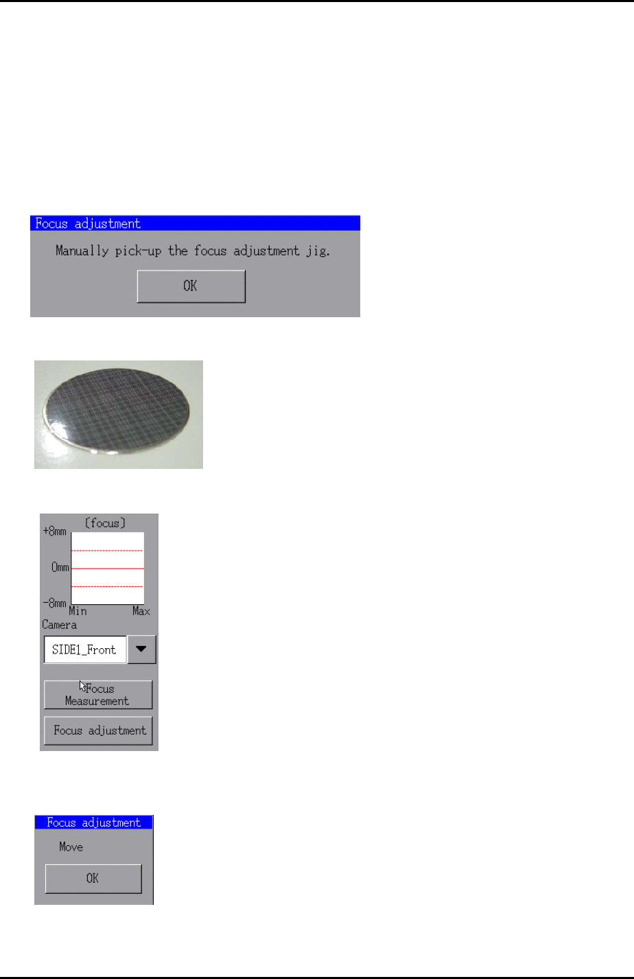
the buzzer sounds release the [START] button. The following message displays:
4. Place the focus jig on the nozzle with the patterned side facing downwards and
press [OK].
Focus jig
5. Select “SIDE1_Front” from the [Camera] drop down list.
6. Select [Focus adjustment] and hold down the [START] button until the following
message appears:
7. Press [OK] and then use the focus ring to adjust the focus on the camera until the
buzzer sounds. This indicates that the focus is within range.
Fuji Machine Mfg. Co., Ltd. Okazaki.
SMT Equipment Quality Assurance Dept.
6 – 15 CS Section
FK-9F98-34 XP Type II Series Training Text for Service Engineers
Edition 2.0 XP242E – Chapter 6 Proper Data Measurements Page 16 of 30
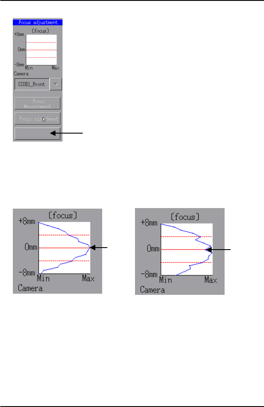
8. To stop the focus adjustment press the following tab:
Complete
Press here to stop the
focus adjustment
9. Now press [Focus Measurement] and hold down the [START] button until the
buzzer sounds.
10. A graph showing the results of the focus measurement appears. The peak of the
graph must be within the dotted red lines indicating +4mm and -4mm. Ideally the
peak of the graph will hit 0mm as shown in the examples below:
Peak at 0
Peak at 0
11. If necessary fine adjust the camera focus until the results of the focus measurement
are within range.
12. Finally apply Loctite 425 adhesive to the focus ring hollow bolt and lock the focus
ring.
13. After locking the focus ring carry out the focus measurement again to confirm that
the focus is still within range.
Fuji Machine Mfg. Co., Ltd. Okazaki.
SMT Equipment Quality Assurance Dept.
6 – 16 CS Section
FK-9F98-34 XP Type II Series Training Text for Service Engineers
Edition 2.0 XP242E – Chapter 6 Proper Data Measurements Page 17 of 30
6.9 Parts Camera Resolution
1. Equipment: glass gage for resolution measurement (Z3502DFAJ0020)
2. Select [Maintenance A] – [I/O Check] – [Y021 Nozzle Unhold] – [OFF] and attach a
20mm nozzle to the placing head.
3. Select [Maintenance A] – [I/O Check] – [Y020 Parts Pickup] – [ON] and attach the
glass gage to the placing head with the printed surface facing downwards.
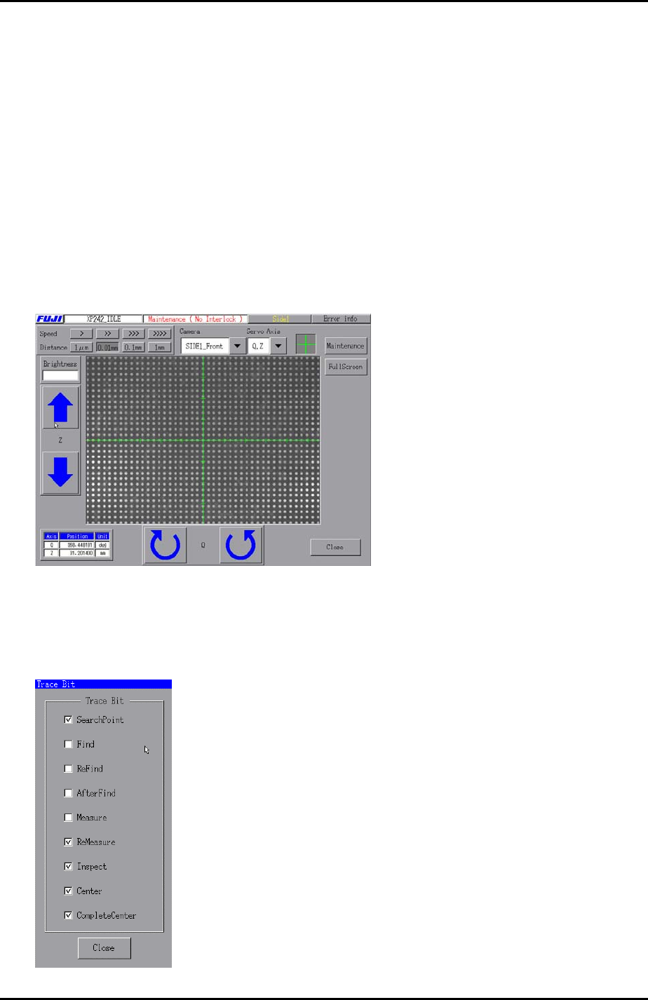
4. Select [Maintenance C] – [Custom Maintenance] and move the Y-axis to the prism
position, and the Z-axis to the part inspection height: Z0 + 27.5mm + 2.5mm
(2.5mm is equivalent to the thickness of the glass gage).
5. Set the center of the cross hairs in the center of one of the central dots on the glass
gage as illustrated below:
6. Select [Maintenance A] – [Trace Bit] and select “SearchPoint”, “ReMeasure”,
“Inspect”, “Center”, and “Complete Center”as shown below:
Fuji Machine Mfg. Co., Ltd. Okazaki.
SMT Equipment Quality Assurance Dept.
6 – 17 CS Section