XP Type II 工程师培训手册 (2.0).pdf.pdf - 第152页
FK-9F98-34 XP T ype II Series T raining T ext for Service Engineers Edition 2.0 XP242E – Chapter 5 Peripheral Adjustm ents Page 14 of 16 5.7 Checking the Power Remover Amplifier (Keyence AP-80A) 1. T urn the M/ C power a…

FK-9F98-34 XP Type II Series Training Text for Service Engineers
Edition 2.0 XP242E – Chapter 5 Peripheral Adjustments Page 13 of 16
3. Use the arrow keys to set the display to “Sor”.
4. Press [SET] once and then use the arrow keys to set the display to “HYS”.
5. Press [SET] once and then use the arrow keys to set the display to “nC”.
6. Press [SET] once and use the arrow keys to set the display to “2.5”.
7. Press [SET] once and use the arrow keys to set the display to “mAn”.
8. Press [SET] once to return to the original screen.
Airblow
1. Press [SET] once, “n_1 and a numerical value “**” flash alternately.
2. Use the arrow keys to set the numerical value to “1.4”.
3. Press [SET] for three seconds.
4. Press [SET] twice to return to original screen.
5. Finally to lock the pressure sensor press [SET] for more than 6 seconds. Use the arrow
keys to select Lock and then press [SET] to return to the original screen.
Fuji Machine Mfg. Co., Ltd. Okazaki.
SMT Equipment Quality Assurance Dept.
5 – 13 CS Section
FK-9F98-34 XP Type II Series Training Text for Service Engineers
Edition 2.0 XP242E – Chapter 5 Peripheral Adjustments Page 14 of 16
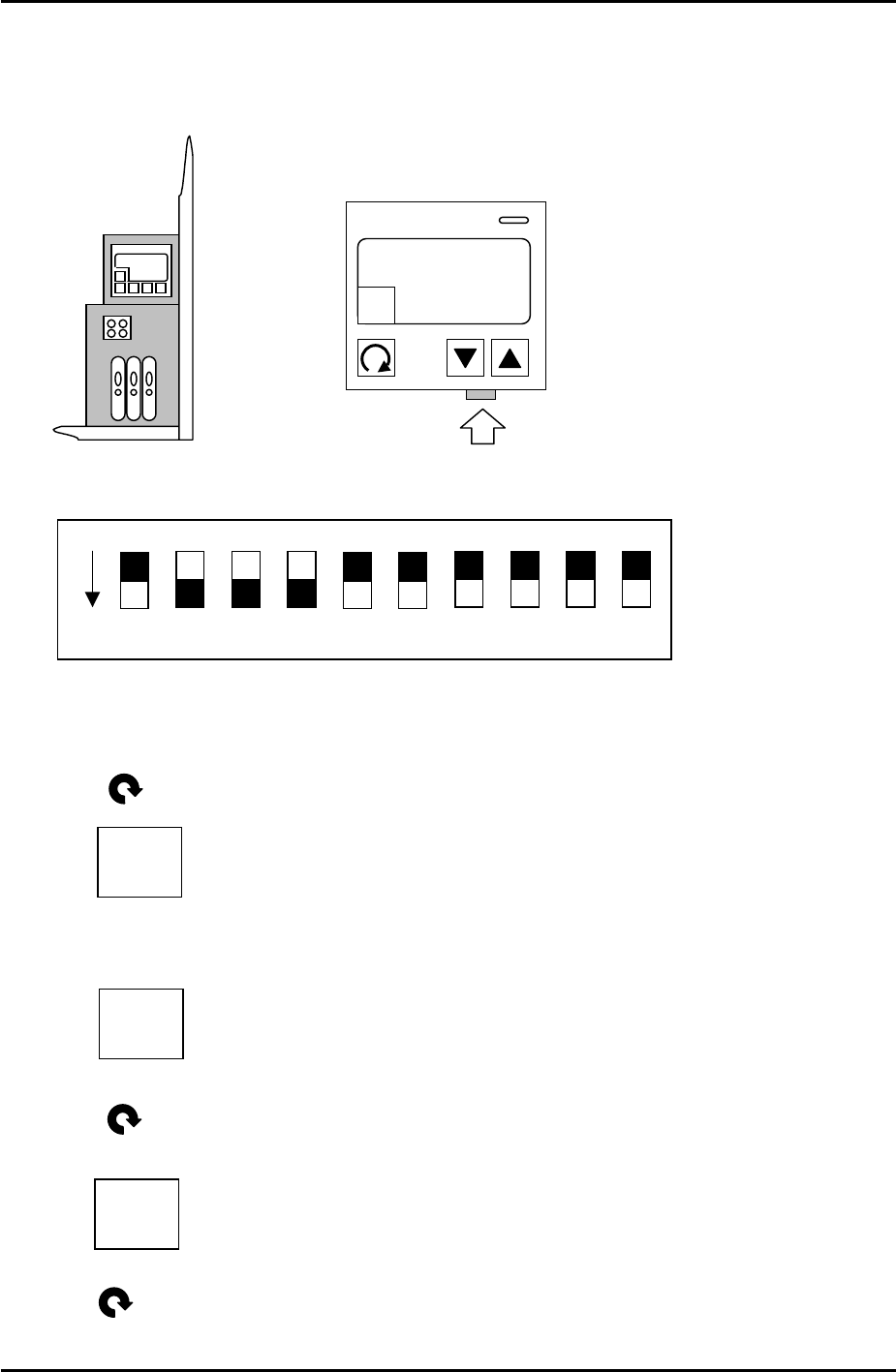
5.7 Checking the Power Remover Amplifier (Keyence AP-80A)
1. Turn the M/C power and breaker OFF.
2. Remove the front cover of the amplifier and set the jumper switches as follows:
3. Power ON.
4. Press once and the following should display:
5. Use the up and down arrow keys to set the value to –5, so the display is like this:
6. Press once and the following should display:
1 – H
“…”
1 – H
-5
ON
DPS-10-B
KEYENCE AP-80A
A
HOLD
1 – h
0
7. Press twice and the setting is finished.
Fuji Machine Mfg. Co., Ltd. Okazaki.
SMT Equipment Quality Assurance Dept.
5 – 14 CS Section
FK-9F98-34 XP Type II Series Training Text for Service Engineers
Edition 2.0 XP242E – Chapter 5 Peripheral Adjustments Page 15 of 16
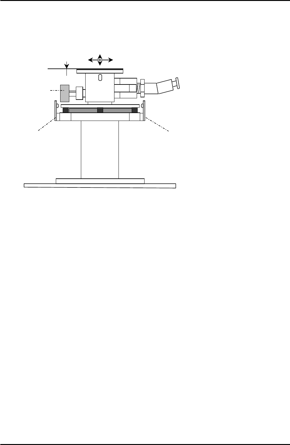
5.8 Adjusting the Power Remover
1. Set the power remover in its station.
Set Check Sensor
Set Check Sensor
Tray pickup
confirmation
2. Select [JOG] and inch the vacuum head close to the remover.
3. Press the emergency button to cut the 200V power supply to the servos. Lower the Z-axis
and stop just before it contacts the remover. Manually jog the position of the X and Y axes
until the pick up head is aligned directly above the remover.
4. Select [Maintenance C] – [Proper Data Editor] – [NOZZLE_POSITION] –
[X_RemoverPos] and [Y_RemoverPos] – [Direct Servo Input] to save the current X and Y
axes positions to proper data.
5. Lower the Z-axis until the pick-up head just contacts the top of the remover, then lower
the head a further 1.0mm. Select [Z_RemoverPos] – [Direct Servo Input] to save the
current Z axis position to proper data.
6. Release the emergency button, and turn the 200V supply to the servos ON. Select
[Production] – [Nozzle Operation] – [Remover] to pick up the remover.
7. Select [Maintenance A] – [I/O Check] – [Y030 RemoverVacuum] – [ON].
8. Confirm that the remover can vacuum a 750 gram tray.
Fuji Machine Mfg. Co., Ltd. Okazaki.
SMT Equipment Quality Assurance Dept.
5 – 15 CS Section