XP Type II 工程师培训手册 (2.0).pdf.pdf - 第38页
FK-9F98-34 XP T ype II Series T raining T ext for Service Engineers Edition 2.0 XP142E – Chapter 4 Loader Adjustment Page 7 of 12 4.5 Main T able Pneumatic Switch Note: Before proceeding with these adjustment s, confirm …
FK-9F98-34 XP Type II Series Training Text for Service Engineers
Edition 2.0 XP142E – Chapter 4 Loader Adjustment Page 6 of 12
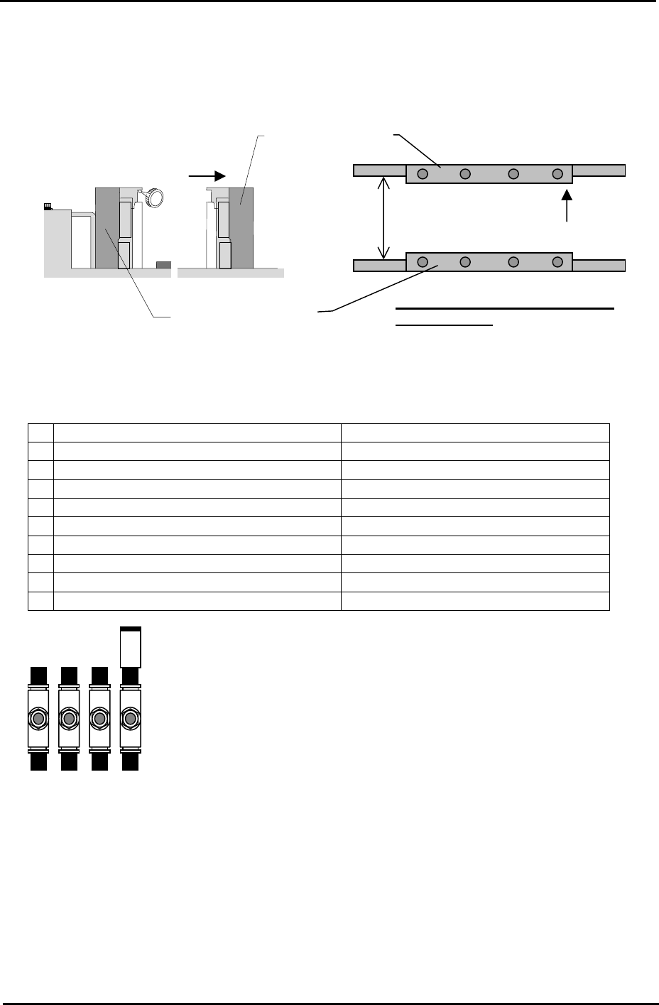
4. Set the dial gage on the fixed rail to “0”, and measure the difference between the fixed rail
and the adjustable rail. Add the difference to the flatness value of the adjustable rail side
measured in step 3. If the values are out of tolerance please contact FUJI.
Reference Conveyor
Viewed from the right
side of the machine
Movable conveyor
200mm
Tolerance: whole deviation to be
within 0.20mm
4.4 Conveyor Speed Controllers
Speed Controller Number of times from fully closed
1 In-conveyor board lifter (UP) Approximately ¼ turn.
2 In-conveyor board lifter (DOWN) Approximately 1 turn.
3
Main conveyor board clamp (SLOW) ½ turn.
4
Main conveyor board unclamp (SLOW) 1.5 turns.
5
Main conveyor board unclamp (FAST) 4 turns.
6
Main conveyor board clamp (FAST) 4 turns.
7 Board stopper (UP) 4 turns.
8 Board stopper (DOWN) 4 turns.
9 Board vacuum (Option) 1 turn.
Note: check the main conveyor board clamp/unclamp speed controller
s
after the main lifter upper limit/downward limit sensor adjustment is
complete.
3 4 5 6
Fuji Machine Mfg. Co., Ltd. Okazaki.
SMT Equipment Quality Assurance Dept.
4 – 6 CS Section
FK-9F98-34 XP Type II Series Training Text for Service Engineers
Edition 2.0 XP142E – Chapter 4 Loader Adjustment Page 7 of 12
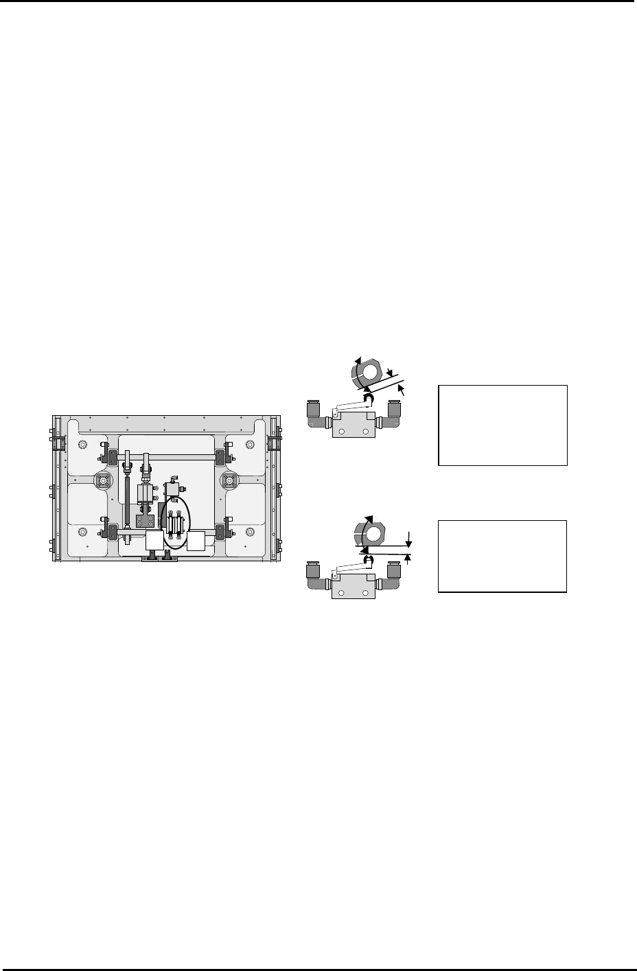
4.5 Main Table Pneumatic Switch
Note: Before proceeding with these adjustments, confirm that the lifter plate flatness
check (4.1) is complete.
Fast Down Adjustment
1. With the lifter plate raised, adjust the position of the cam so that there is a gap of 1mm
between the cam and the pneumatic switch roller.
Fast Up Adjustment
2. With the lifter plate raised, adjust the position of the cam so that it is horizontal.
2
1
1. Fast Down cam.
1mm gap with lifte
r
raised
Machine front.
2
1
2. Fast UP cam.
Horizontal with lifte
r
raised
Machine rear under the main table.
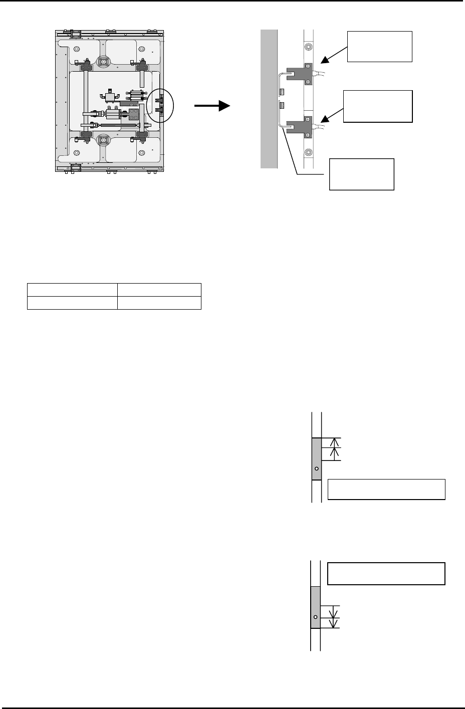
4.6 Lifter Upper/Lower Limit Sensor
1. Raise the main lifter and adjust the flag so that the upper limit sensor turns ON when a
4mm thick board is clamped, and turns OFF when a 4.8mm thick board is clamped.
2. With the main lifter lowered, adjust the flag at the lower limit sensor side so that it is
positioned 1mm past the point where the sensor comes ON.
3. Ensure that the I/O [X024 MainStLftUpChk] is ON when the lifter is at its upper limit, and
[X025 MainStLftDwnChk] is ON when the lifter is at its lower limit.
Fuji Machine Mfg. Co., Ltd. Okazaki.
SMT Equipment Quality Assurance Dept.
4 – 7 CS Section
FK-9F98-34 XP Type II Series Training Text for Service Engineers
Edition 2.0 XP142E – Chapter 4 Loader Adjustment Page 8 of 12
Table
Front of the
machine
Upper limit
sensor
Lower limit
senso
r
Adjust the
fla
g
Checking the Lifter Speed
1. Select [Manual Operation] – [Conveyor Operation] – [Main Lifter Up/Down] to raise and
lower the main lifter. The travel time should be in the following range:
Moving UP 400 – 600 ms
Moving DOWN 700 – 900 ms
Note: If the travel time is not in the range, re-adjust the main lifter speed controllers.
4.7 Main Stopper
Measuring jig: Plate jig (AJPJ-0060)
Main stopper down
Sensor OFF
Sensor ON: raise 1mm
Fix the Sensor
1. Select [Maintenance A] – [I/O Check] – and turn [Y02A
MainStationStp] OFF to lower the main stopper.
2. Lower the lower limit sensor [I/O X01F
MainStStpOffChk] until it turns OFF.
3. Raise the lower limit sensor, and lock the sensor 1mm
above the point it first turns ON.
Main stopper up
Sensor OFF
Sensor ON: Lower 1mm
Fix the sensor
4. 4.Select [Maintenance A] – [I/O Check], and turn ON
I/O [Y02A MainStationStop] to raise the main stopper.
5. Raise the upper limit sensor [I/O X01E
MainStStpOnChk] until it turns OFF.
6. Lower the upper limit sensor, and fasten the sensor
1mm below the point the sensor first comes ON.
Fuji Machine Mfg. Co., Ltd. Okazaki.
SMT Equipment Quality Assurance Dept.
4 – 8 CS Section