XP Type II 工程师培训手册 (2.0).pdf.pdf - 第46页
FK-9F98-34 XP T ype II Series T raining T ext for Service Engineers Edition 2.0 XP142E – Chapter 5 Peripheral Adjustm ents Page 2 of 14 5.2 MFU Device T able Measurement 1. Use a dial gage to measure device surfaces A an…
FK-9F98-34 XP Type II Series Training Text for Service Engineers
Edition 2.0 XP142E – Chapter 5 Peripheral Adjustments Page 1 of 14
Chapter 5 – Peripheral Adjustments
5.1 MFU Height and Clamping Adjustment
1. Adjust the MFU air valve speed controllers as described in the following table:
Speed controller location Number of turns from fully closed Function
On cylinder 2 turns from fully closed Unclamp
On air line 3.5 turns from fully closed Clamp
2. Confirm that there is no jolting when clamping and unclamping the MFU. If necessary
make slight adjustments to the speed controllers to achieve smooth clamping and
unclamping.
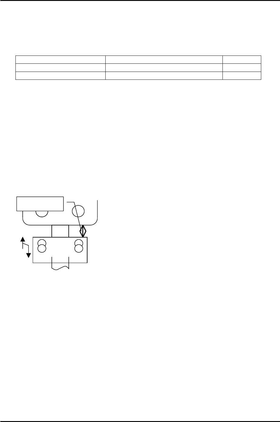
3. Clamp the MFU.
Warning: the MFU device table is very heavy; please take extreme care to prevent your
finger/hand getting caught when carrying out height or other adjustments on the MFU.
4. Adjust the MFU height adjustment stopper, so that when the MFU is clamped, the gap
between the stopper and the MFU device table underside is approximately 20mm.
Please see the following diagram:
A
pprox. 20mm
Fuji Machine Mfg. Co., Ltd. Okazaki
SMT Equipment Quality Assurance Dept.
5 – 1 CS Section
FK-9F98-34 XP Type II Series Training Text for Service Engineers
Edition 2.0 XP142E – Chapter 5 Peripheral Adjustments Page 2 of 14
5.2 MFU Device Table Measurement
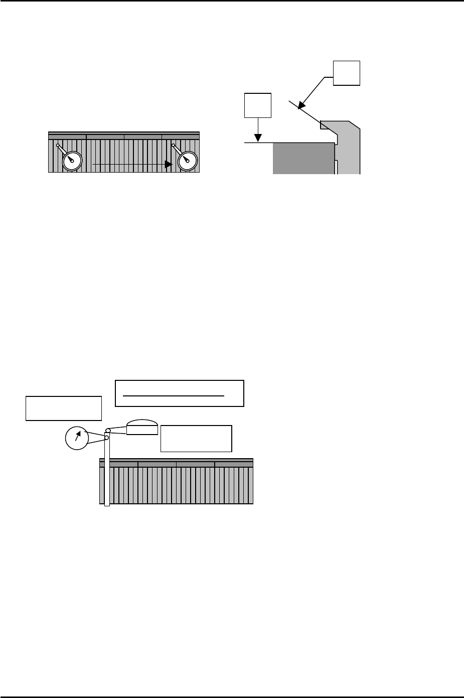
1. Use a dial gage to measure device surfaces A and B. Please refer to the diagram below:
A
D50
D1
0
B
2. Tolerance is 0.05mm/800mm.
3. Measure the second MFU and any additional MFUs in the same manner.
Y and Z Direction Static Accuracy
1. Choose one MFU as the reference and clamp it at side 1.
2. Mount the device jig in slot No. 2 and use an extension bar to attach the two dial gages to
the placement head.
3. Put the tip of the dial gages against the end of the device jig in the Y and the Z directions.
Please refer to the following illustration:
Z-direction
Y-direction
Tolerance: ±0.035mm
4. Set the dial gages to 0 and jog the head away from the device jig in the X direction.
Record the current Y-axis counter value and then unclamp the MFU.
5. In place of the reference MFU clamp the second MFU or any additional MFUs at side 1.
6. Mount the device jig in slot No. 2 and turn the servo power ON. Ensure the Y counter
value is the same as that recorded in step 4 and then jog the head in the X direction until
the dial gages contact the device jig in the Y and Z directions.
7. Check the difference between the reference MFU and the second (or additional MFUs) in
the Z and Y directions. Tolerance is +/- 0.035mm. If out of tolerance please contact
FUJI.
Fuji Machine Mfg. Co., Ltd. Okazaki
SMT Equipment Quality Assurance Dept.
5 – 2 CS Section
FK-9F98-34 XP Type II Series Training Text for Service Engineers
Edition 2.0 XP142E – Chapter 5 Peripheral Adjustments Page 3 of 14
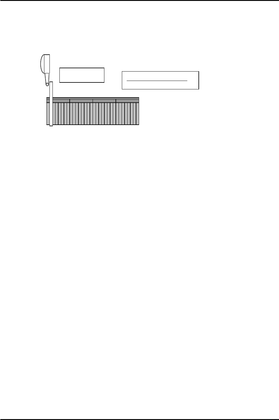
X Direction Static Accuracy
1. Clamp the reference MFU used in previous steps to side 1.
2. Mount the device jig in slot No.2 and set the dial gage tip against the jig in the X direction.
Please refer to the illustration below:
X-direction
Tolerance: ±0.035mm
3. Set the dial to 0 and then jog the head in the Y direction to slide the dial gage tip away
from the jig.
4. Record the current X-axis servo counter value and then unclamp the MFU.
5. Clamp the second MFU (or any additional MFUs) and mount the device jig in slot No.2
and turn the servo ON.
6. Ensure the X axis counter value is the same as that recorded in step 4 and then jog the
head in the Y direction until the dial gage tip contacts the jig.
7. Check the difference between the reference MFU and the second MFU (or any additional
MFUs) in the X-direction. Tolerance is +/- 0.035mm.
Fuji Machine Mfg. Co., Ltd. Okazaki
SMT Equipment Quality Assurance Dept.
5 – 3 CS Section