XP Type II 工程师培训手册 (2.0).pdf.pdf - 第193页
C C h h a a p p t t e e r r 8 8 T T y y p p e e I I I I M M T T U U A A d d j j u u s s t t m m e e n n t t
FK-9F98-34 XP Type II Series Training Text for Service Engineers
Edition 2.0 XP242E – Chapter 7 Checking Operation and Accuracy Page 6 of 6
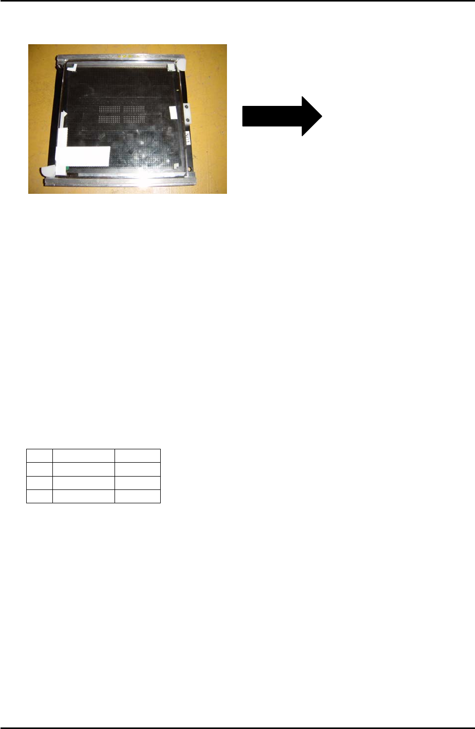
9. Remove the board from the conveyor and place it in the reverse measurement holder.
The surface upon which the components were placed should be facing down:
Insert in conveyor
in this direction
(Left to Right
conveyor). Plastic
stopper is at the
right of the holder.
10. Change the conveyor width to 198.5mm.
11. Load the reverse measurement holder in the conveyor and select [Conveyor Operation] –
[Load New Panel] to clamp the holder and board in the main table.
12. Select [Maintenance C] – [Accuracy Measurement] – and turn [Place Offset
Measurement Mode] ON.
13. Press [Select Program] – and select “ReverseAM-F-192-S1.PGO”.
14. Select [Reverse Start] – [START] to start the measurement.
15. Once measurement is complete the “Accuracy Measurement Result” window opens.
Press [Side1 Offset] – [OK] to save the offsets.
16. Remove the holder from the conveyor and replace the tape on the glass board, repeating
steps 6 to 15 until the results are within the following tolerance:
Average 3∑
X
+/- 0.020 0.050
Y
+/- 0.020 0.050
Q
+/- 0.200 1.500
Side 2
1. Repeat for side 2 using “ReverseAM-F-192-S2.PGO”.
Fuji Machine Mfg. Co., Ltd. Okazaki
SMT Equipment Quality Assurance Dept.
7–6 CS Section

C
C
h
h
a
a
p
p
t
t
e
e
r
r
8
8
T
T
y
y
p
p
e
e
I
I
I
I
M
M
T
T
U
U
A
A
d
d
j
j
u
u
s
s
t
t
m
m
e
e
n
n
t
t
FK-9F98-34 XP Series Type II Training Text for Service Engineers
Edition 2.0 XP242E – Chapter 8 Type II MTU Adjustment Page 1 of 18
Chapter 8 – Type II MTU Adjustment
8.1 Proper Data
1. Select [OPERATION] – [TrayDetectMotion] and set to 0 during the adjustment and to 2
afterwards.
2. Select [OPERATION_2] – [JogInterlockOFF] and set to 1 during the adjustment and to 0
afterwards.
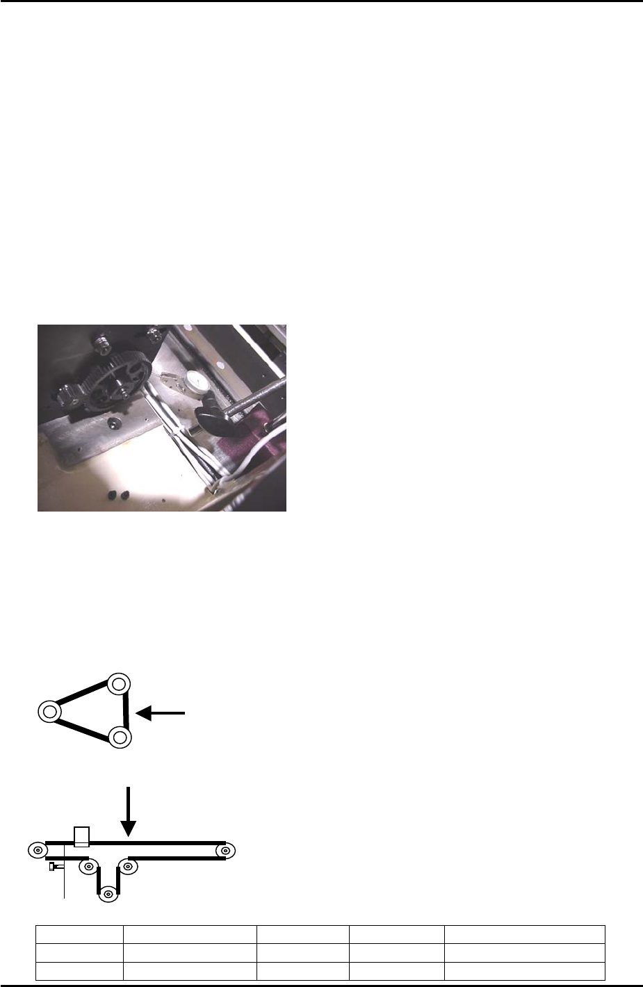
8.2 U Axis Backlash Check
1. Use a dial gage to check the backlash of the large gear as shown in the photo below.
When checking the backlash the small gear should be held so it does not move. The
backlash should be in the range 0.08mm to 0.15mm. If the backlash is not in the range
loosen the installation bolts for the large gear and adjust as required.
8.3 Belt Tension
1. When measuring the U axis belt tension it is necessary to put the shuttle against the
minus mechanical stopper.
2. Refer to the following illustrations and check that the tension of each belt is within the
correct range:
T axis measuring point
U axis measuring point
Belt unit weight Belt width Belt span Frequency range
T axis
2.5gf/mm 15mm 151mm 147 +/- 7 Hz
U axis
0.25gf/mm 9mm 566mm 37 ~ 41 Hz
Fuji Machine Mfg. Co., Ltd. Okazaki
SMT Equipment Quality Assurance Dept.
8 – 1 CS Section