XP Type II 工程师培训手册 (2.0).pdf.pdf - 第130页
FK-9F98-34 XP T ype II Series T raining T ext for Service Engineers Edition 2.0 XP242E – Chapter 4 Loader Adjustment Page 5 of 12 Fuji Machine Mfg. Co., Ltd. Okazaki. SMT Equipment Quality Assu rance Dept. 4 – 5 CS Secti…

FK-9F98-34 XP Type II Series Training Text for Service Engineers
Edition 2.0 XP242E – Chapter 4 Loader Adjustment Page 4 of 12
Post Adjustment Checks:
1. Ensure that the clamper motion is smooth when the main table is raised and lowered.
2. Ensure there is sufficient clearance between the back-up pins and the under side of a
clamped board.
3. Confirm that the minimum (0.5mm) thick board and the maximum (4.0mm) board can be
clamped correctly.
Fuji Machine Mfg. Co., Ltd. Okazaki.
SMT Equipment Quality Assurance Dept.
4 – 4 CS Section
FK-9F98-34 XP Type II Series Training Text for Service Engineers
Edition 2.0 XP242E – Chapter 4 Loader Adjustment Page 5 of 12
Fuji Machine Mfg. Co., Ltd. Okazaki.
SMT Equipment Quality Assurance Dept.
4 – 5 CS Section
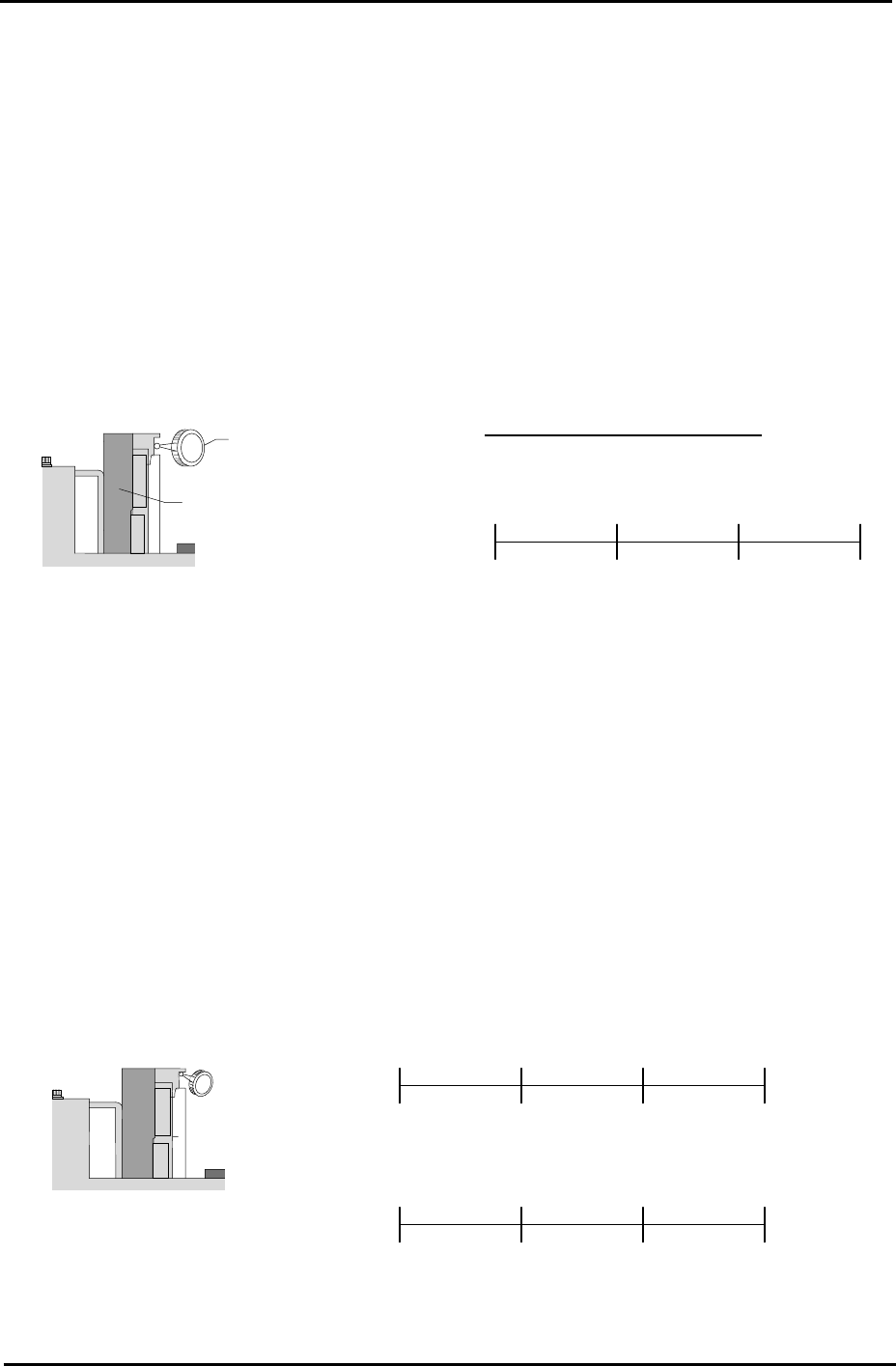
4.3 Conveyor Rails
Rail Parallelism
1. Attach a dial guage to the placing head (an extension bar is necesarry).
2. Set the dial gauge on the fixed conveyor rail.
3. Set the dial gage to “0”. Measure the parallelism of the fixed rail.
4. Record your measurements on the adjustments check sheet:
Dial Gauge
Reference side of the
Conveyor
Tolerance: ±0.05 / 450 mm
(mm) 150 450 300 0
( ) ( ) ( ) (mm) 0
Viewed from the right side
of the machine
Rail Flatness
1. Adjust the conveyor width to 200mm.
2. Set the dial gauge on the underside of the board clamper at the fixed rail side. Measure the
flatness and record the measurements on the adjustment check sheet.
450 300 150 0
(mm)
Reference side of th
conveyor
e
( )
Viewed from the right
side of the machine
0
450 300 150
( ) ( ) ( )
0
( ) ( ) ( ) (mm)
(mm)
(mm)
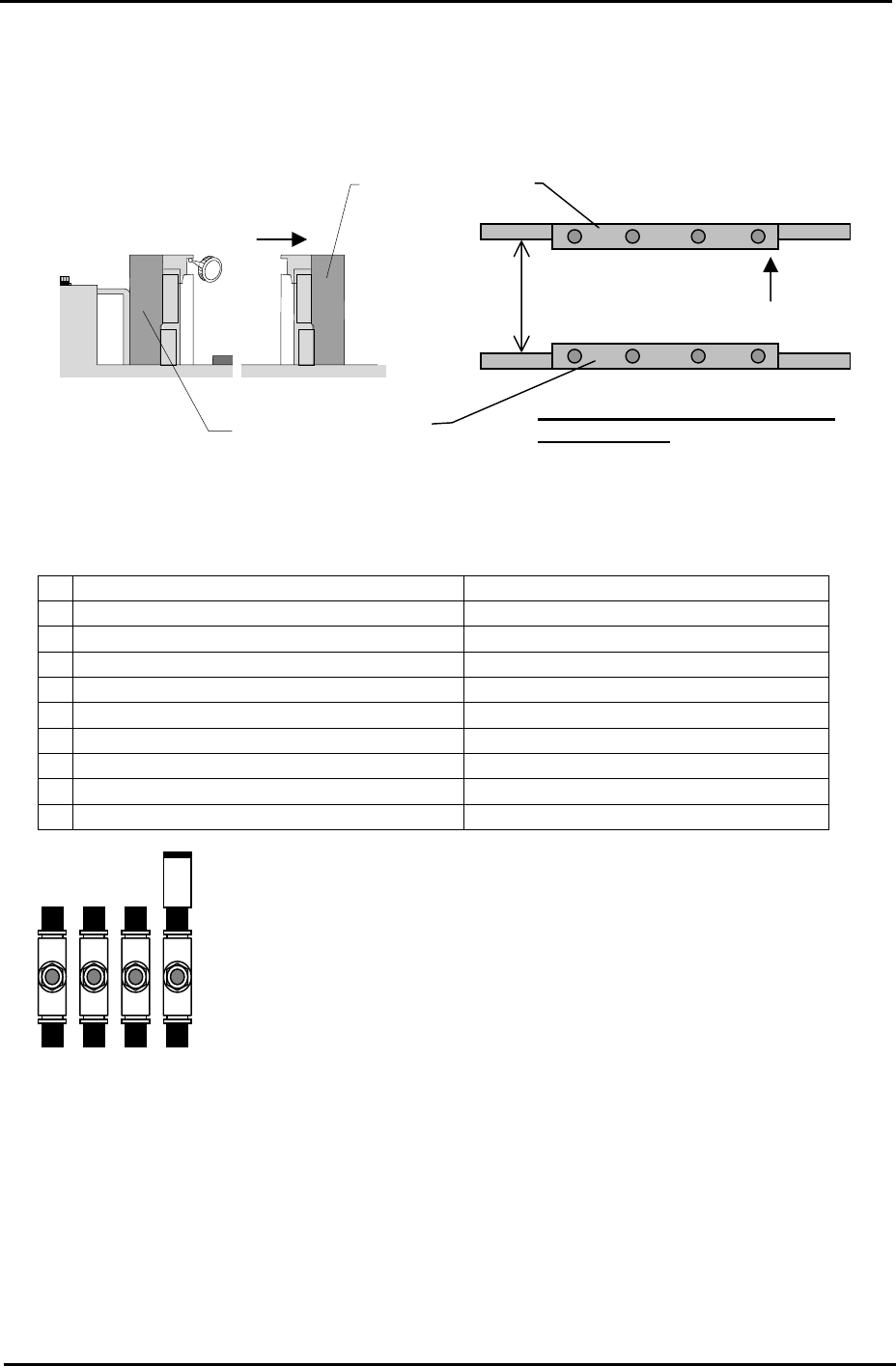
3. Measure the flatness of the underside of the board clamper at the adjustable rail side.
FK-9F98-34 XP Type II Series Training Text for Service Engineers
Edition 2.0 XP242E – Chapter 4 Loader Adjustment Page 6 of 12
4. Set the dial gage on the fixed rail to “0”, and measure the difference between the fixed rail
and the adjustable rail. Add the difference to the flatness value of the adjustable rail side
measured in step 3. If the values are out of tolerance please contact FUJI.
Reference Conveyor
Viewed from the right
side of the machine
Movable conveyor
200mm
Tolerance: whole deviation to be
within 0.20mm
4.4 Conveyor Speed Controllers
Speed Controller Number of times from fully closed
1 In-conveyor board lifter (UP) Approximately ¼ turn.
2 In-conveyor board lifter (DOWN) Approximately 1 turn.
3
Main conveyor board clamp (SLOW) ½ turn.
4
Main conveyor board unclamp (SLOW) 1.5 turns.
5
Main conveyor board unclamp (FAST) 4 turns.
6
Main conveyor board clamp (FAST) 4 turns.
7 Board stopper (UP) 4 turns.
8 Board stopper (DOWN) 4 turns.
9 Board vacuum (Option) 1 turn.
Note: check the main conveyor board clamp/unclamp speed controller
s
after the main lifter upper limit/downward limit sensor adjustment is
complete.
3 4 5 6
Fuji Machine Mfg. Co., Ltd. Okazaki.
SMT Equipment Quality Assurance Dept.
4 – 6 CS Section