XP Type II 工程师培训手册 (2.0).pdf.pdf - 第52页
FK-9F98-34 XP T ype II Series T raining T ext for Service Engineers Edition 2.0 XP142E – Chapter 5 Peripheral Adjustm ents Page 8 of 14 5.4 MFU Interlock Sensors 1. Clamp the MFU and set two sensor adjustment jig s (Z963…

FK-9F98-34 XP Type II Series Training Text for Service Engineers
Edition 2.0 XP142E – Chapter 5 Peripheral Adjustments Page 7 of 14
14. Press the dial once so that the “2” in “2P” flashes.
15. Block the sensor by hand and press the dial switch once. A number 1~100 will display
on the digital display, this must be greater than 10.
16. Press the dial switch once so that SET flashes in the mode display.
17. Turn the dial switch so that RUN flashes in the mode display.
18. Press the dial switch once to complete the adjustment.
19. Finally select [Maintenance A] – [I/O Check] and check the sensor operation by I/O.
Side 1
Sensor I/O Output when not
interrupted
Output when
interrupted
F1 X02C Side1TpsetDetect1 O (with buzzer) X
F2 X029 Side1TpSetDetect2 O (with buzzer) X
20. Repeat the whole procedure for the sensors and amplifiers at side 2.
Side 2
Sensor I/O Output when not
interrupted
Output when
interrupted
F1 X03C Side2TpSetDetect1 O (with buzzer) X
F2 X02B Side2TpSetDetect2 O (with buzzer) X
Fuji Machine Mfg. Co., Ltd. Okazaki
SMT Equipment Quality Assurance Dept.
5 – 7 CS Section
FK-9F98-34 XP Type II Series Training Text for Service Engineers
Edition 2.0 XP142E – Chapter 5 Peripheral Adjustments Page 8 of 14
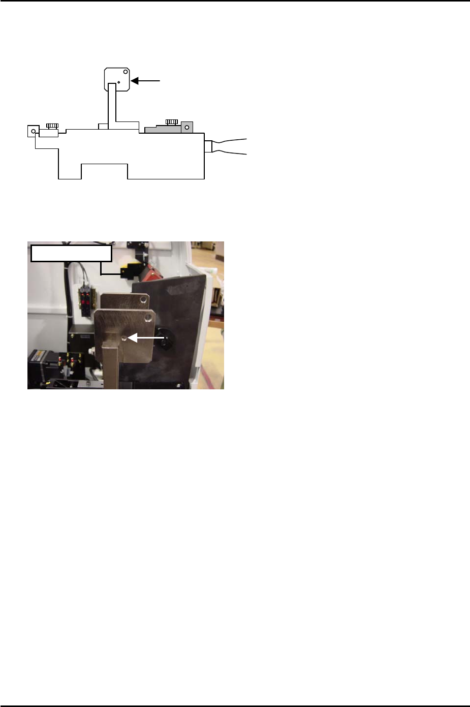
5.4 MFU Interlock Sensors
1. Clamp the MFU and set two sensor adjustment jigs (Z9631ADEPJ8070) at slots D47
and D49 at side 1.
Attachment Plate
Z9631ADEPJ8070
Fuji Machine Mfg. Co., Ltd. Okazaki
2. Adjust the position of the interlock sensors so that the light beam goes through the holes
in the attachment plates.
Hole
Interlock Sensor
SMT Equipment Quality Assurance Dept.
5 – 8 CS Section
FK-9F98-34 XP Type II Series Training Text for Service Engineers
Edition 2.0 XP142E – Chapter 5 Peripheral Adjustments Page 9 of 14
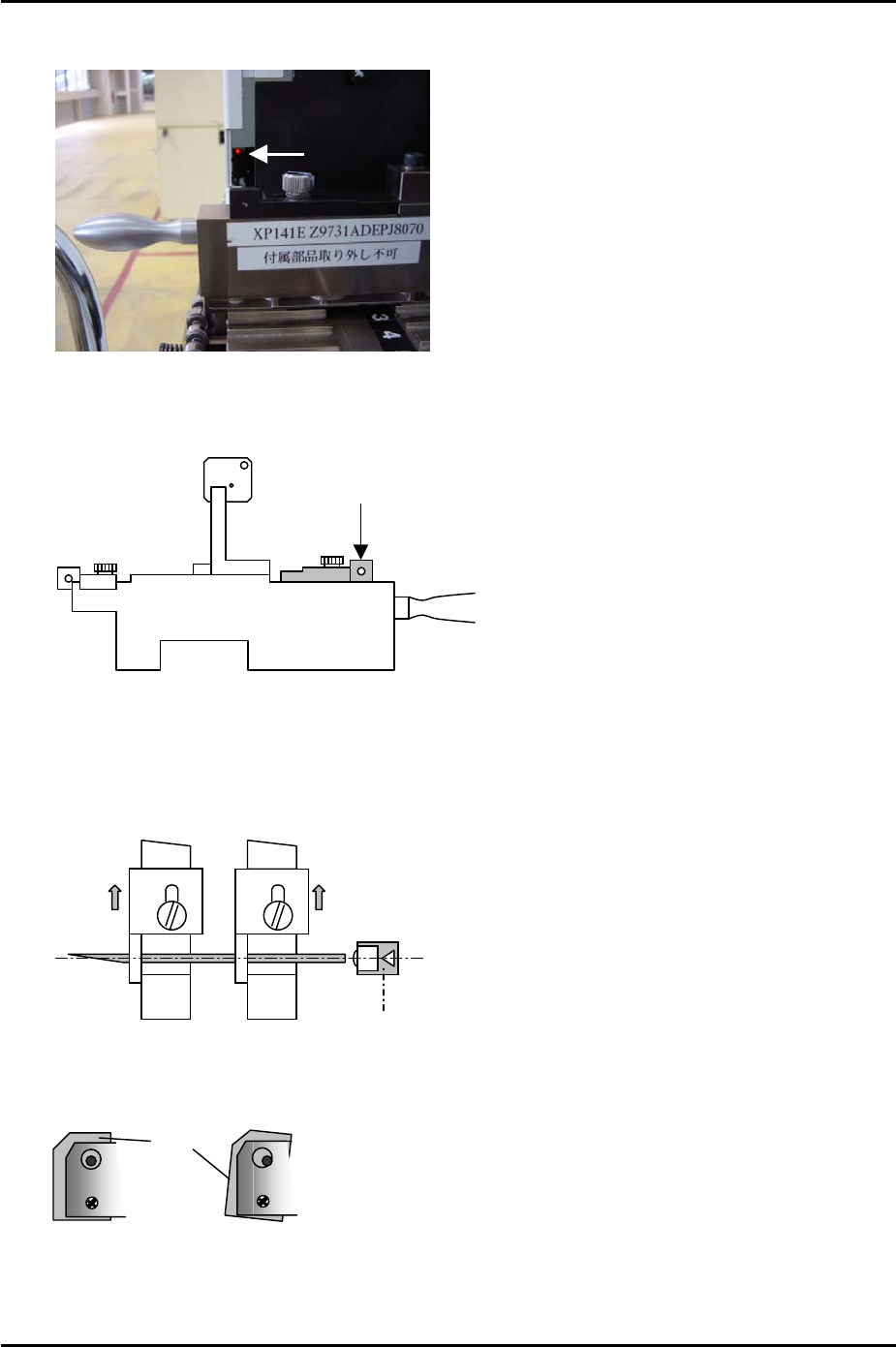
5.5 Feeder Set Check Sensors
Feeder
Set Chec
k
Sensor
1. Clamp the MFU and set two sensor adjustment jigs (Z9631ADEPJ8070) at slots D47
and D49 at side 1.
Rear Sliding
A
ttachment
Z9631ADEPJ8070
2. Fix the rear sliding attachments at their forward limit (in the direction towards the
machine interior) and insert a 1.8mm diameter wire jig between the holes in the
attachments. Adjust the feeder set check sensor position so that the point where the
sensor beam is emitted is aligned with the center of the wire jig.
D47
D49
Feeder set check sensor
3. Check the tilt of both sensors.
BKT
Sensor
BKT
4. Use I/O [X017] Side1XYAxisInter to monitor the signal.
5. Repeat for side 2 using I/O [X01A] Side2XYAxisInter to monitor the signal.
Fuji Machine Mfg. Co., Ltd. Okazaki
SMT Equipment Quality Assurance Dept.
5 – 9 CS Section