XP Type II 工程师培训手册 (2.0).pdf.pdf - 第75页
FK-9F98-34 XP T ype II Series T raining T ext for Service Engineers Edition 2.0 XP142E – Chapter 6 Proper Dat a Measurement s Page 16 of 30 10. Confirm that the resolution result s are within the tolerances shown below: …
FK-9F98-34 XP Type II Series Training Text for Service Engineers
Edition 2.0 XP142E – Chapter 6 Proper Data Measurements Page 15 of 30
6.11 Mark Camera Resolution Measurement
1. Equipment: mark camera resolution measurement jig (Z3502DEAJ0020).
2. Clamp the resolution jig in the main conveyor. It should be flush with the reference rail,
and the printed surface should be uppermost.
3. Select [Maintenance C] – [Custom Maintenance] – [Fiducial] – the fiducial lamp comes
ON and the mark camera live image is displayed on the screen.
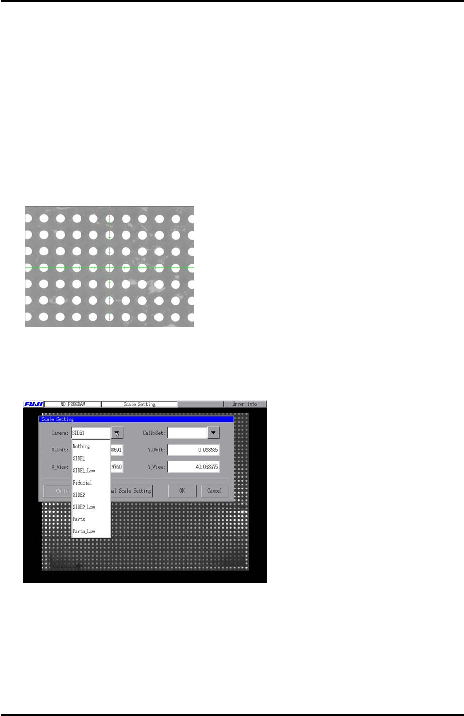
4. Inch the mark camera over the center of the resolution jig.
5. Select the cross hairs and set the center of the cross hairs in the center of the resolution
jig center dot.
6. Select [Close] to exit Maintenance Mode and then select [Maintenance A] – [Scale
Setting] and choose [Fiducial] from the drop down list. Select “1.0 [mm] pitch WHITE”
from the [CalibSet] drop down list.
7. Select [Calibration] and answer YES to the question “Set Center?” and the resolution
measurement will proceed.
8. Answer NO to the question “Do you save calibration data to FD?”
9. To the next question “Save Calibration Data?” answer YES.
Fuji Machine Mfg. Co., Ltd. Okazaki
SMT Equipment Quality Assurance Dept.
6 – 15 CS Section
FK-9F98-34 XP Type II Series Training Text for Service Engineers
Edition 2.0 XP142E – Chapter 6 Proper Data Measurements Page 16 of 30
10. Confirm that the resolution results are within the tolerances shown below:
Mark camera resolution tolerance
X_Unit
0.0140 ~ 0.0147
X_View
8.90 ~ 9.50
Y_Unit
0.0140~ 0.0147
Y_View
6.56 ~ 6.95
11. The resolution measurement is now complete, press [OK] to return to the [Maintenance
A] screen.
6.12 Mark Positions and Angle Measurement
1. Select [Maintenance A] – [Jog] – [Fiducial] – the fiducial lamp comes ON and the mark
camera live image is displayed on the screen.
2. Select the cross hairs and then center the mark camera in the center of the parts gage
station left hand fiducial mark
{.
{
|
}
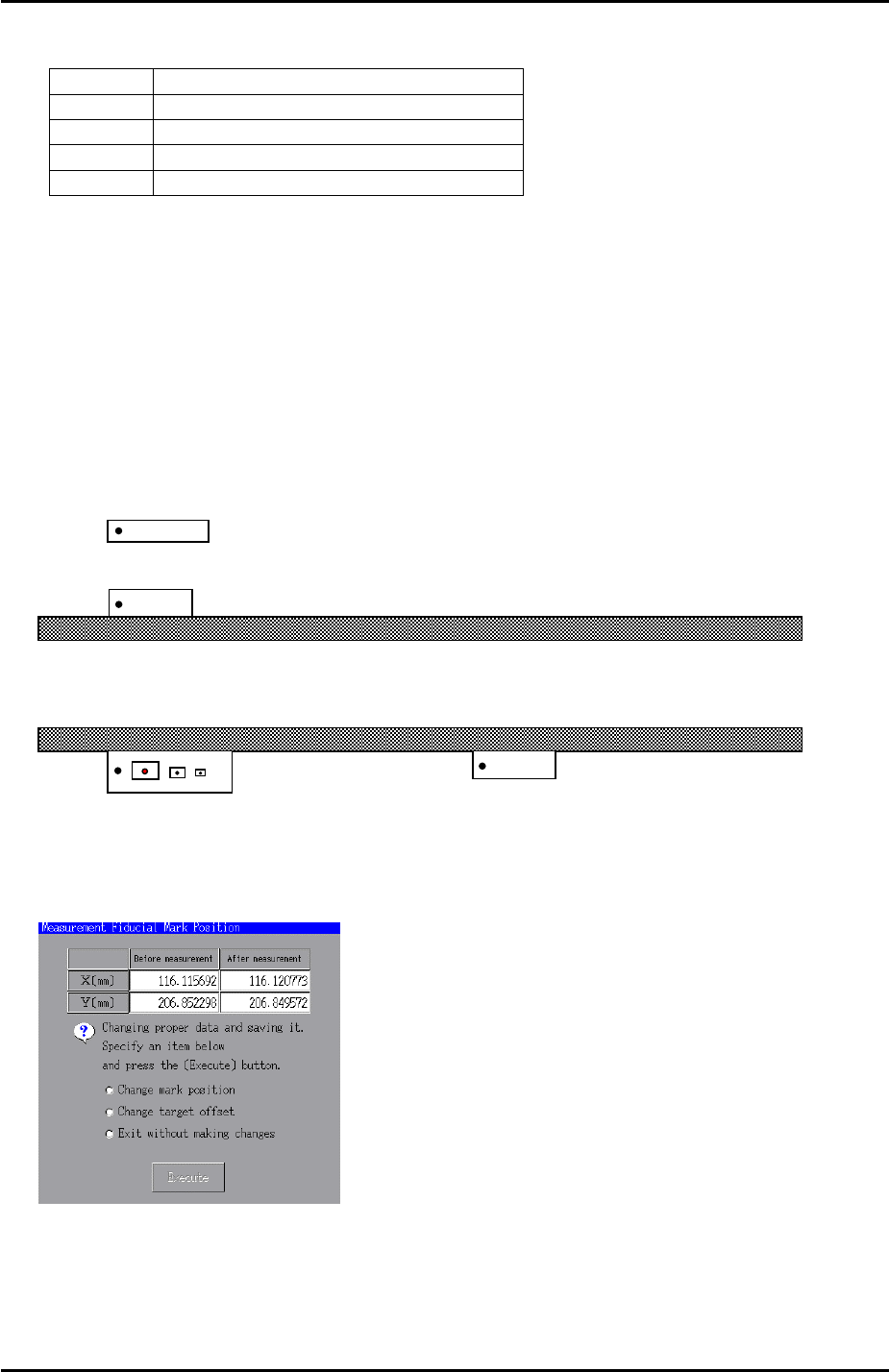
3. Select [Maintenance C] – [Mark Camera Measurement] – [F MarkPos Measure] –
[START] to measure the position of the fiducial mark. The following dialogue box will
then display:
4. Select [Change mark position] – [Execute] and the results of the measurement will be
automatically saved in [Proper Data Editor] – [OTHERS] – [X_MeasureFidMark] and
[Y_MeasureFidMark].
Fuji Machine Mfg. Co., Ltd. Okazaki
SMT Equipment Quality Assurance Dept.
6 – 16 CS Section
FK-9F98-34 XP Type II Series Training Text for Service Engineers
Edition 2.0 XP142E – Chapter 6 Proper Data Measurements Page 17 of 30
5. With the mark camera still centered on fiducial mark { select [Angle Measure] – [START]
to measure the mark camera Q (theta) orientation. To save the calibration results press
[OK].
6. Now select [Maintenance C] – [Custom Maintenance] – [Fiducial] and center the mark
camera on fiducial mark
|. Select [Maintenance] – [Proper Data Editor] – [OTHERS] –
[X_MeasureFidMark2] and [Y_MeasureFidMark2] – [Direct Servo Input] to save the
current position in proper data.
7. Return to the Maintenance Mode jog screen and center the mark camera on fiducial mark
}. Select [Maintenance] – [Proper Data Editor] – [OTHERS] – [X_MeasureFidMark3] and
[Y_MeasureFidMark3] – [Direct Servo Input] to save the current position in proper data.
6.13 Measuring the Board Origin
1. Select [Maintenance A] – [I/O Check] – [Y02A Main StationSt] – and raise the main
stopper.
2. Select [Maintenance A] – [Jog] – [Fiducial] and display the cross hairs on the screen.
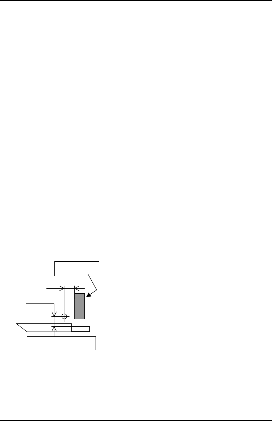
3. Set the vertical cross hair flush with the left side of the main stopper and then use the
inching tabs (in step mode) to move the X axis exactly 5mm in the minus direction.
4. Select [Maintenance C] – [Proper Data Editor] – [Machine Origin] – [X_board Origin] –
[Direct Servo Input] to save the current position to proper data.
5. Return to the [JOG] screen and set the horizontal cross hair flush with the side of the
reference rail and then use the inching tabs to move the Y axis 5.25mm in the plus
direction.
6. Select [Maintenance C] – [Proper Data Editor] – [Machine Origin] – [Y_board Origin] –
[Direct Servo Input] to save the current position to proper data.
5.0 mm
5.25 mm
Side of the reference rail
Main Stopper
Fuji Machine Mfg. Co., Ltd. Okazaki
SMT Equipment Quality Assurance Dept.
6 – 17 CS Section