XP Type II 工程师培训手册 (2.0).pdf.pdf - 第92页
FK-9F98-34 XP T ype II Series T raining T ext for Service Engineers Edition 2.0 XP142E – Chapter 7 Operation and Accuracy Page 2 of 8 7.2 Glass Part s P AM Side 1 1. Equipment: glass board (Z9731DNPJ002*), glass part s (…

FK-9F98-34 XP Type II Series Training Text for Service Engineers
Edition 2.0 XP142E – Chapter 7 Operation and Accuracy Page 1 of 8
Chapter 7 – Operation and Accuracy
7.1 Checking Idle Operation
1. Transmit the idle program “XP142_IDLE” to the machine.
2. Press [Production] – [Select Program] – [XP142_IDLE] – [Download] to bring the program
into the machine foreground.
3. Press [Production] – [Nozzle Editor] and configure the nozzle editor entries as shown in
the following table:
Nozzle Number Nozzle Diameter (mm)
1 1.3
2 1.3
3 1.3
4 1.3
5 1.3
6 1.3
7 1.3
8 1.3
9 1.3
10 1.3
11 1.3
12 1.3
4. Arrange the nozzles in the revolver so that they match the nozzle editor configuration.
5. Set the conveyor at its maximum width of 356mm.
6. Select [Maintenance A] – [Operation Settings] and set the mode as detailed in the
following table:
Operation Mode Idle1 (use Idle2 if any feeders are loaded in the MFU)
Production Mode Automatic
Error Handling Error Stop
Acceleration Rate 0.1
7. Check for any mechanical interference in the machine then select [Production] –
[Automatic] – [Start] to commence idling.
8. Check that there are no irregular noises or movements in the machine and then gradually
increase the acceleration rate up to the maximum of 1.
9. The machine should be run for at least 12 hours without stopping, and in total for at least
30 hours.
10. After idling is complete check the machine for any irregularities.
Fuji Machine Mfg. Co., Ltd. Okazaki
SMT Equipment Quality Assurance Dept.
7 – 1 CS Section
FK-9F98-34 XP Type II Series Training Text for Service Engineers
Edition 2.0 XP142E – Chapter 7 Operation and Accuracy Page 2 of 8
7.2 Glass Parts PAM
Side 1
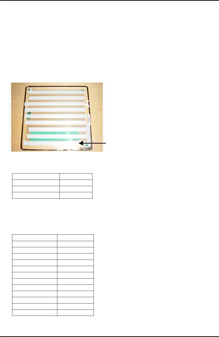
1. Equipment: glass board (Z9731DNPJ002*), glass parts (Z9731DNPJ364*), Pick up
platform jig (Z9734DNPJ123*).
2. Select [Production] – [Nozzle Center Measurement] – [Side1] – acceleration rate [1.0] –
[Rotate Center Measurement] to carry out rotate center measurement. Carry this out at
least three times prior to PAM measurement.
3. Put double sided tape on the board as shown in the photo below:
The tape should cover the first 4
rows of dots at the bottom of the
board, then there is a gap of 3
rows of dots before the next strip
of tape covers 4 rows of dots and
so on.
4. Select [Maintenance A] – [Operation Settings] – and make the following settings:
Operation Mode Production
Production Mode Automatic
Error handling Error Stop
Accel. Rate 1.00
5. Set the conveyor width to 178mm.
6. Set the following nozzles in the revolver and in the nozzle editor:
Nozzle number Nozzle Size
1 5mm
2 Empty
3 Empty
4 5mm
5 Empty
6 Empty
7 5mm
8 Empty
9 Empty
10 5mm
11 Empty
12 Empty
Fuji Machine Mfg. Co., Ltd. Okazaki
SMT Equipment Quality Assurance Dept.
7 – 2 CS Section
FK-9F98-34 XP Type II Series Training Text for Service Engineers
Edition 2.0 XP142E – Chapter 7 Operation and Accuracy Page 3 of 8
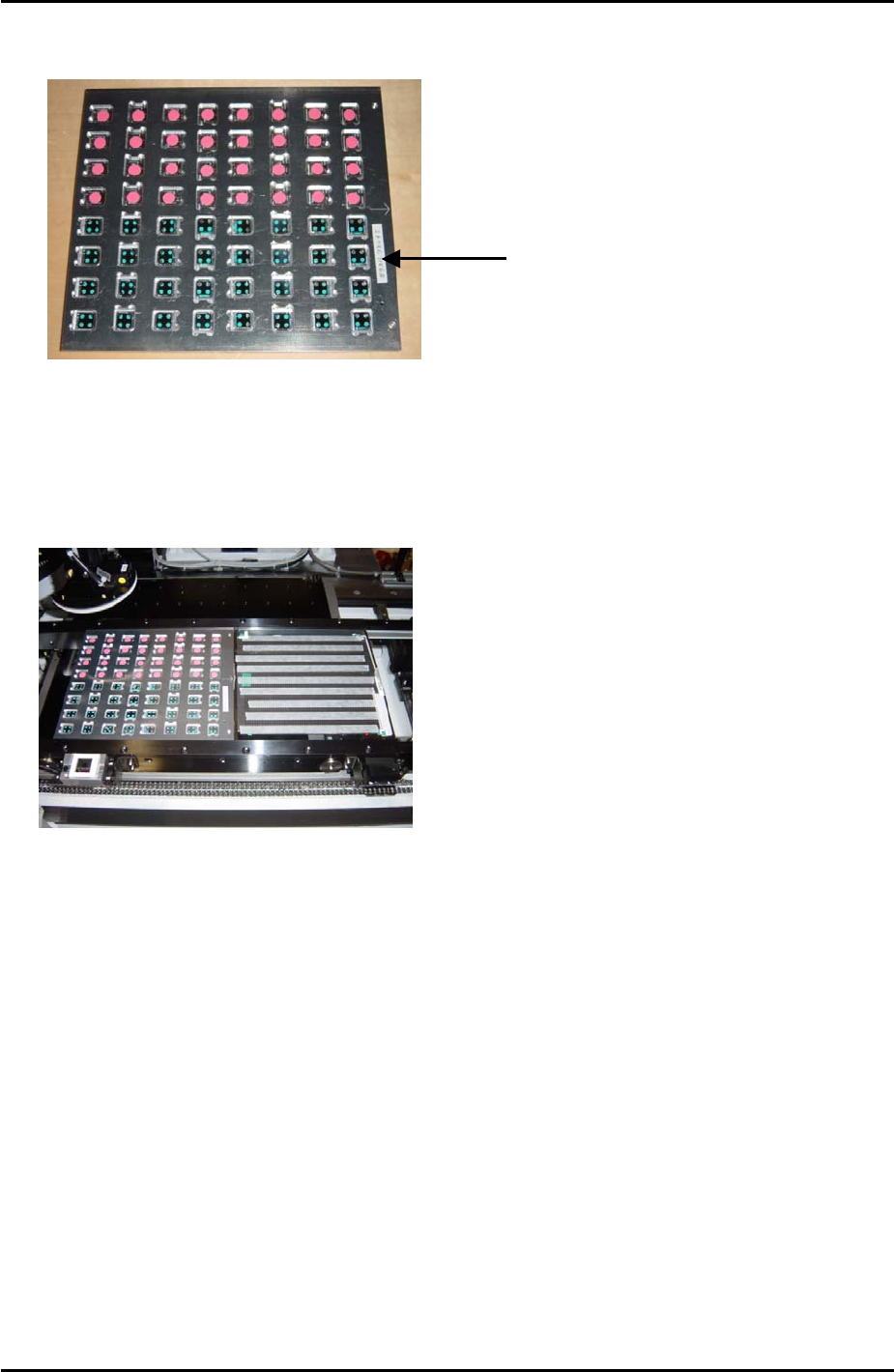
7. Load the glass parts in the front half of the pickup platform jig as shown in the photo
below:
Glass parts are picked
up from the front hal
f
of the pick up jig
8. Load the pick up platform jig and the glass board in the main conveyor.
9. Check for interference and then select [Maintenance C] – [Glass Gauge Measurement] –
[READY ON] – [Stopper Up] to raise the main stopper. Put the glass board and pick up
platform jig against the stopper as shown in the photo below, then select [Clamp] –
[START] to clamp the main conveyor:
10. Select [Side1] – [Start] – [START] and the machine picks up the parts and places them on
the glass board.
11. When parts placement is completed and a message appears press [START] to carry out
measurement.
Fuji Machine Mfg. Co., Ltd. Okazaki
SMT Equipment Quality Assurance Dept.
7 – 3 CS Section