XP Type II 工程师培训手册 (2.0).pdf.pdf - 第180页
FK-9F98-34 XP T ype II Series T raining T ext for Service Engineers Edition 2.0 XP242E – Chapter 6 Proper Data Mea surement s Page 25 of 30 4. Select [Maintenance C] – [Proper data editor] – [Jig Position] – [X _Jig Pick…
FK-9F98-34 XP Type II Series Training Text for Service Engineers
Edition 2.0 XP242E – Chapter 6 Proper Data Measurements Page 24 of 30
6. Select [Maintenance C] – [Proper data editor] – [Machine Origin] –
[X_Stage1Org/Y_Stage1Org] – [Direct servo input] to save the current X and Y
axes positions in proper data.
7. Select [Maintenance A] – [I/O Check] – [Y021 NozzleUnhold] – [OFF] and attach
the nozzle jig to the placing head.
8. Manually bring the nozzle jig above the surface of the MFU pick up position
measurement jig surface and descend the Z-axis until the nozzle jig contacts the
surface.
9. Select [Maintenance C] – [Proper data editor] – [Machine Origin] –
[Z_Stage1surface] – [Direct servo input] to save the current Z-axis position in
proper data.
10. In situations where the MFU pick up position measurement jig is unavailable, a
normal feeder may be used. In this case align the fiducial camera center on the
component in the parts pick up cavity and save the X and Y positions in proper data
by following the procedure above. Set the Z_Stage1surface proper data where a
0.7 diameter nozzle first contacts the component surface.
6.16 Glass Gage Position
1. Equipment: Nozzle jig (Z9531DEPJ0070). Glass gage (BVDZ-0140).
2. Select [Maintenance A] – [Jog] – [Fiducial] – and display the cross hairs on the
screen.
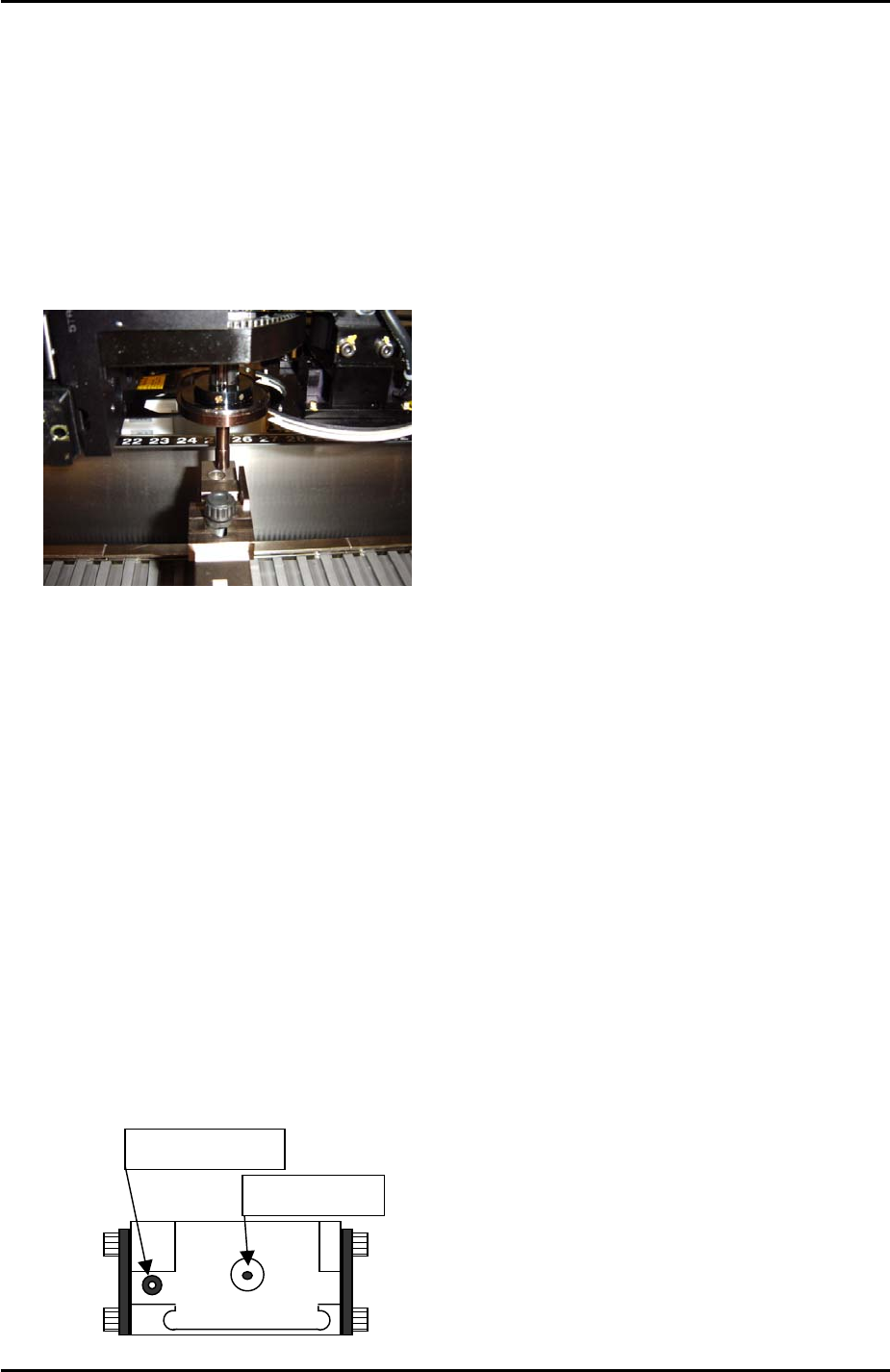
3. Inch the X and Y axes until the fiducial camera is centered on the glass gage
station vacuum hole.
Vacuum hole
Fiducial Mark
Fuji Machine Mfg. Co., Ltd. Okazaki.
SMT Equipment Quality Assurance Dept.
6 – 24 CS Section
FK-9F98-34 XP Type II Series Training Text for Service Engineers
Edition 2.0 XP242E – Chapter 6 Proper Data Measurements Page 25 of 30
4. Select [Maintenance C] – [Proper data editor] – [Jig Position] – [X_Jig Pick Pos1/
Y_Jig Pick Pos] – [Direct servo input] to save the current X and Y axes positions in
proper data.
5. Select [Maintenance A] – [I/O Check] – [Y021 NozzleUnhold] – [OFF] and attach
the nozzle jig to the placing head.
6. Set the glass gage in the glass gage station and inch the nozzle jig above the glass
gage.
7. Press the emergency stop button to cut the 200-volt power supply to the servos and
then manually lower the Z-axis until the nozzle jig contacts the surface of the glass
gage.
8. Select [Maintenance C] – [Proper data editor] – [Jig position] – [Z_Jig Pick Pos] –
[Direct servo input] to save the current Z-axis position in proper data.
6.17 Fixed Mark Positions
1. In addition to the fiducial mark on the glass gage station, the position of two other
marks must be saved in proper data.
2. Select [Maintenance A] – [Jog] – [Fiducial] – and display the cross hairs on the
screen.
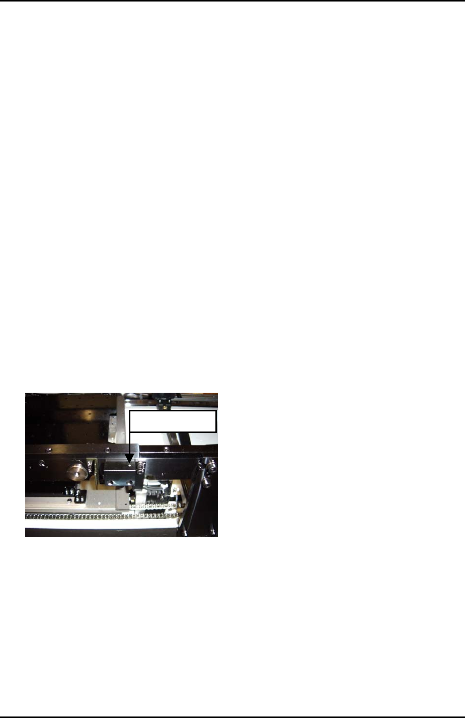
3. Inch the X and Y axes until the fiducial camera is centered on “fiducial mark 2”
shown below:
Fiducial Mark 2
4. Select [Maintenance C] – [Proper Data Editor] – [Others] –
[X_MeasureFidMark2/Y_MeasureFidMark2] – [Direct Servo Input] to save the
current X and Y axes positions in proper data.
5. Return to the jog screen and inch the X and Y axes until the fiducial camera is
centered on “fiducial mark 3” shown below:
Fuji Machine Mfg. Co., Ltd. Okazaki.
SMT Equipment Quality Assurance Dept.
6 – 25 CS Section
FK-9F98-34 XP Type II Series Training Text for Service Engineers
Edition 2.0 XP242E – Chapter 6 Proper Data Measurements Page 26 of 30
Fiducial Mark 3
6. Return to [Proper Data Editor] – [Others] – [X_MeasureFidMark3/
Y_MeasureFidMark3] – [Direct Servo Input] to save the current X and Y axes
positions in proper data.
6.18 Matrix Data
1. Equipment: glass gage for matrix measurement (A5704DEAJ14013).
2. Note that the matrix data measurement should be carried out when the machine is
cold, otherwise the results will not be reliable. Fuji recommends that the machine is
not used for at least two hours prior to the measurement.
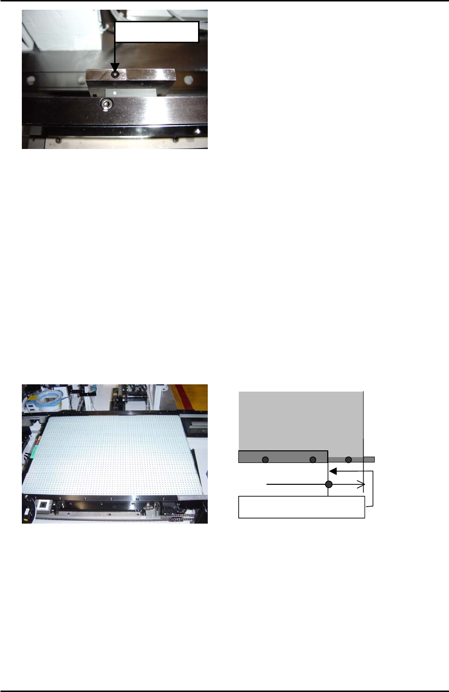
3. Set the conveyor width to its maximum (356.00mm).
4. Clamp the matrix measurement glass gage approximately 70mm from the main
conveyor right end.
Approx. 70mm
Main conveyor right end
Glass gauge for matrix data
(A5704DEAJ1013)
5. Because the glass gage is 5mm thick the main lifter upper limit sensor will not come
ON when the gage is clamped. As a result it is necessary to interrupt the upper
limit sensor with a piece of paper tape.
6. Select [Maintenance A] – [Jog] – [Fiducial] – and display the cross hairs on the
screen.
7. Center the fiducial camera on the last dot in the bottom left hand corner of the glass
gage and record the Y-axis counter value.
8. Move the fiducial camera until it is centered on the last dot in the bottom right hand
corner of the glass gage. Compare the current Y-axis counter value with that
Fuji Machine Mfg. Co., Ltd. Okazaki.
SMT Equipment Quality Assurance Dept.
6 – 26 CS Section