XP Type II 工程师培训手册 (2.0).pdf.pdf - 第195页
FK-9F98-34 XP Series T ype II T raining T ext for Service Engineers Edition 2.0 XP242E – Chapter 8 T ype II MTU Adjustment Page 2 of 18 8.4 T -T ray Origin (magazin e adjustment and measurement) 1. Jog the T -axis until …
FK-9F98-34 XP Series Type II Training Text for Service Engineers
Edition 2.0 XP242E – Chapter 8 Type II MTU Adjustment Page 1 of 18
Chapter 8 – Type II MTU Adjustment
8.1 Proper Data
1. Select [OPERATION] – [TrayDetectMotion] and set to 0 during the adjustment and to 2
afterwards.
2. Select [OPERATION_2] – [JogInterlockOFF] and set to 1 during the adjustment and to 0
afterwards.
8.2 U Axis Backlash Check
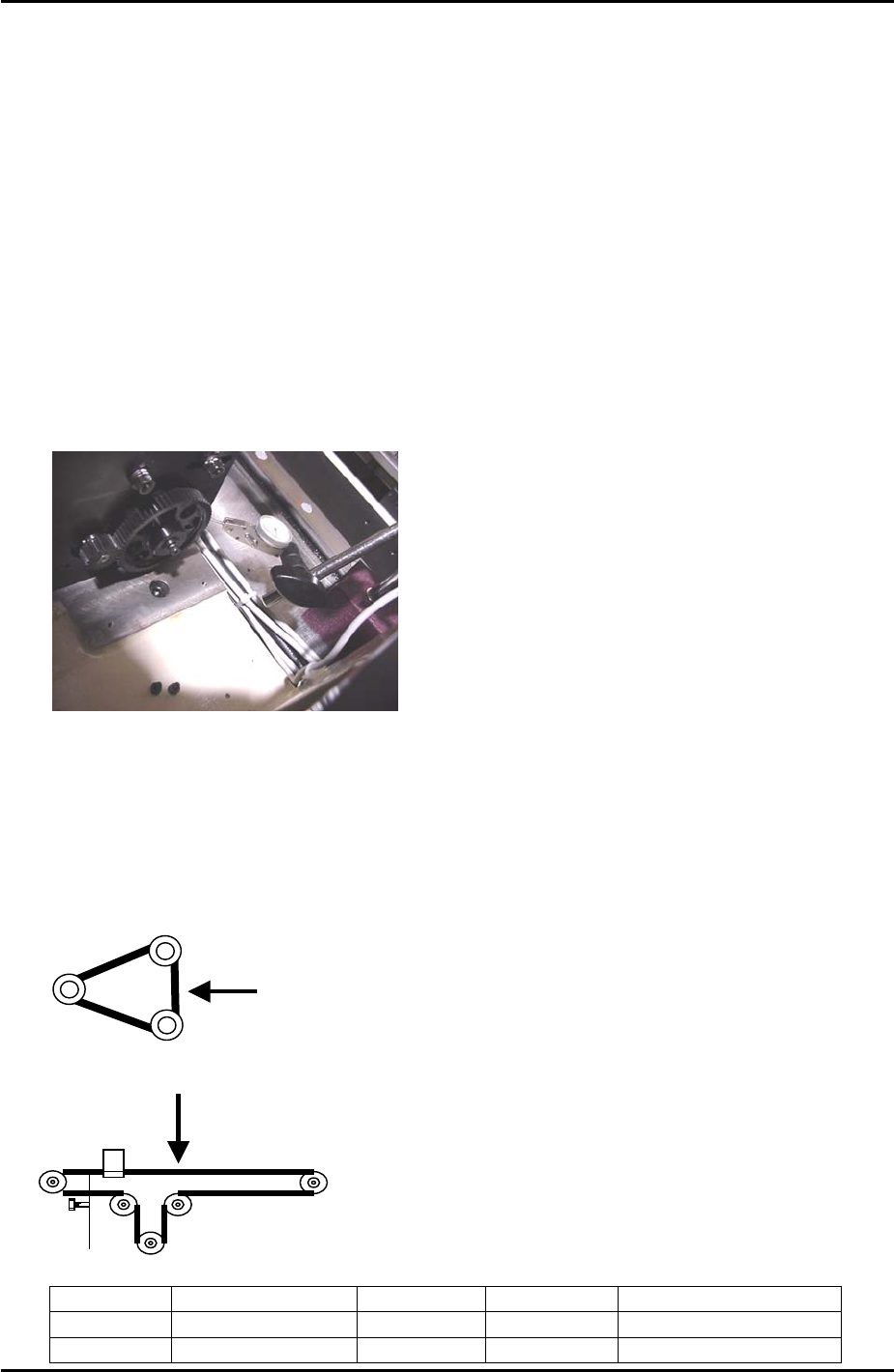
1. Use a dial gage to check the backlash of the large gear as shown in the photo below.
When checking the backlash the small gear should be held so it does not move. The
backlash should be in the range 0.08mm to 0.15mm. If the backlash is not in the range
loosen the installation bolts for the large gear and adjust as required.
8.3 Belt Tension
1. When measuring the U axis belt tension it is necessary to put the shuttle against the
minus mechanical stopper.
2. Refer to the following illustrations and check that the tension of each belt is within the
correct range:
T axis measuring point
U axis measuring point
Belt unit weight Belt width Belt span Frequency range
T axis
2.5gf/mm 15mm 151mm 147 +/- 7 Hz
U axis
0.25gf/mm 9mm 566mm 37 ~ 41 Hz
Fuji Machine Mfg. Co., Ltd. Okazaki
SMT Equipment Quality Assurance Dept.
8 – 1 CS Section
FK-9F98-34 XP Series Type II Training Text for Service Engineers
Edition 2.0 XP242E – Chapter 8 Type II MTU Adjustment Page 2 of 18
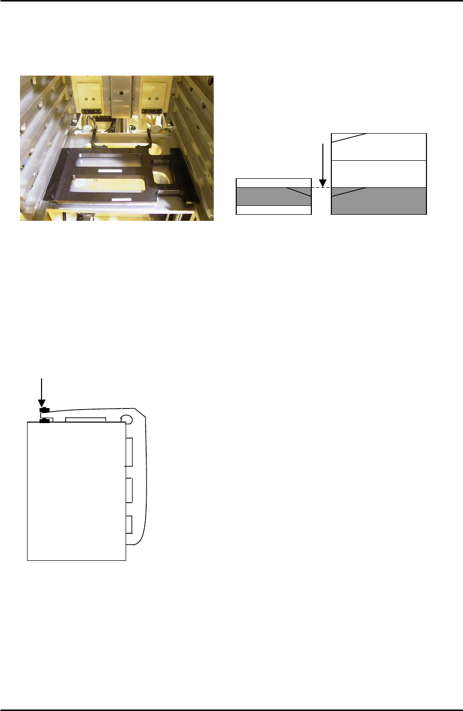
8.4 T-Tray Origin (magazine adjustment and measurement)
1. Jog the T-axis until the right hand side of slot [41,42] is level with the U axis conveyor rail.
Use the dial gages and jig (Z9731ADEPJ8131):
U axis
The U axis conveyor
and slot [41,42] of the
magazine are level
Magazine [41,42]
2. With the T-axis in the same position measure the height difference between the left side
of slot [41, 42] and the U axis conveyor rail. The height of the magazine slot should be
0.03mm higher than that of the U axis conveyor rail. The reason for this is that the MTU
magazine is fixed at the right hand side (when viewed from the machine rear) but not at
the left-hand side. When trays and tray parts are loaded on the left-hand side it is
weighed down and lowers slightly in relation to the right hand side.
3. If necessary adjust the height of the left hand side of slot [41,42] using the bolt on top of
the magazine, see diagram below:
Adjust here
4. Jog the T axis so that slot [01,02] is roughly level with the U axis conveyor rail.
5. Use the dial gage and jig to find the position where the right hand side of slot [01,02] is
0.04mm above the U axis conveyor rail.
6. Select [Maintenance C] – [Proper Data Editor] – [TRAY] – [T_TrayOrg] – [Direct Servo
Input] to save the current T axis position as “T_TrayOrg” in proper data.
Fuji Machine Mfg. Co., Ltd. Okazaki
SMT Equipment Quality Assurance Dept.
8 – 2 CS Section
FK-9F98-34 XP Series Type II Training Text for Service Engineers
Edition 2.0 XP242E – Chapter 8 Type II MTU Adjustment Page 3 of 18
8.5 Guide Rail Adjustment
1. Place an empty tray pallet in slot [01,02] and bring it to the “T_TrayOrg” position.
2. Adjust the upper guide rails so that they are 9mm above the tray pallet surface.
3. Adjust the lower guide rails so that they are 19mm beneath the upper guide rails.
Tray Pallet
9mm
19mm
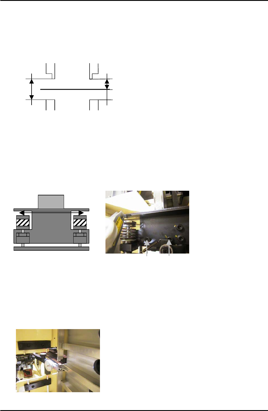
8.6 U Axis Clamper Parallelism Check and Adjustment
1. Use an extension bar to attach a dial gage to the placing head and adjust the parallelism
of the U axis shuttle so that it is parallel to the X-axis. Tolerance is 0.03mm. Refer to the
diagram and photo below:
To adjust the parallelism loosen these
two bolts
MC Front
8.7 Shuttle Rail Position Adjustment
1. Use a dial gage to measure the width of all the slots. Find the average slot to use as a
reference, refer to the photo below:
Use a dial gage to measure the width
of all the slots, and use the slot with
an average width as the reference.
Fuji Machine Mfg. Co., Ltd. Okazaki
SMT Equipment Quality Assurance Dept.
8 – 3 CS Section