XP Type II 工程师培训手册 (2.0).pdf.pdf - 第189页
FK-9F98-34 XP T ype II Series T raining T ext for Service Engineers Edition 2.0 XP242E – Chapter 7 Checking Operation and Accuracy Page 3 of 6 8. Load the pick up platfor m jig and the glass board in the main conveyor . …
FK-9F98-34 XP Type II Series Training Text for Service Engineers
Edition 2.0 XP242E – Chapter 7 Checking Operation and Accuracy Page 2 of 6
7.2 Glass Parts PAM
Side 1
1. Equipment: glass board (Z9731DNPJ002*), glass parts (Z9731DNPJ364*), Pick up
platform jig (Z9734DNPJ123*).
2. Select [Production] – [Nozzle Center Measurement] – [Side1] – acceleration rate [1.0] –
[Rotate Center Measurement] to carry out rotate center measurement. Carry this out at
least three times prior to PAM measurement.
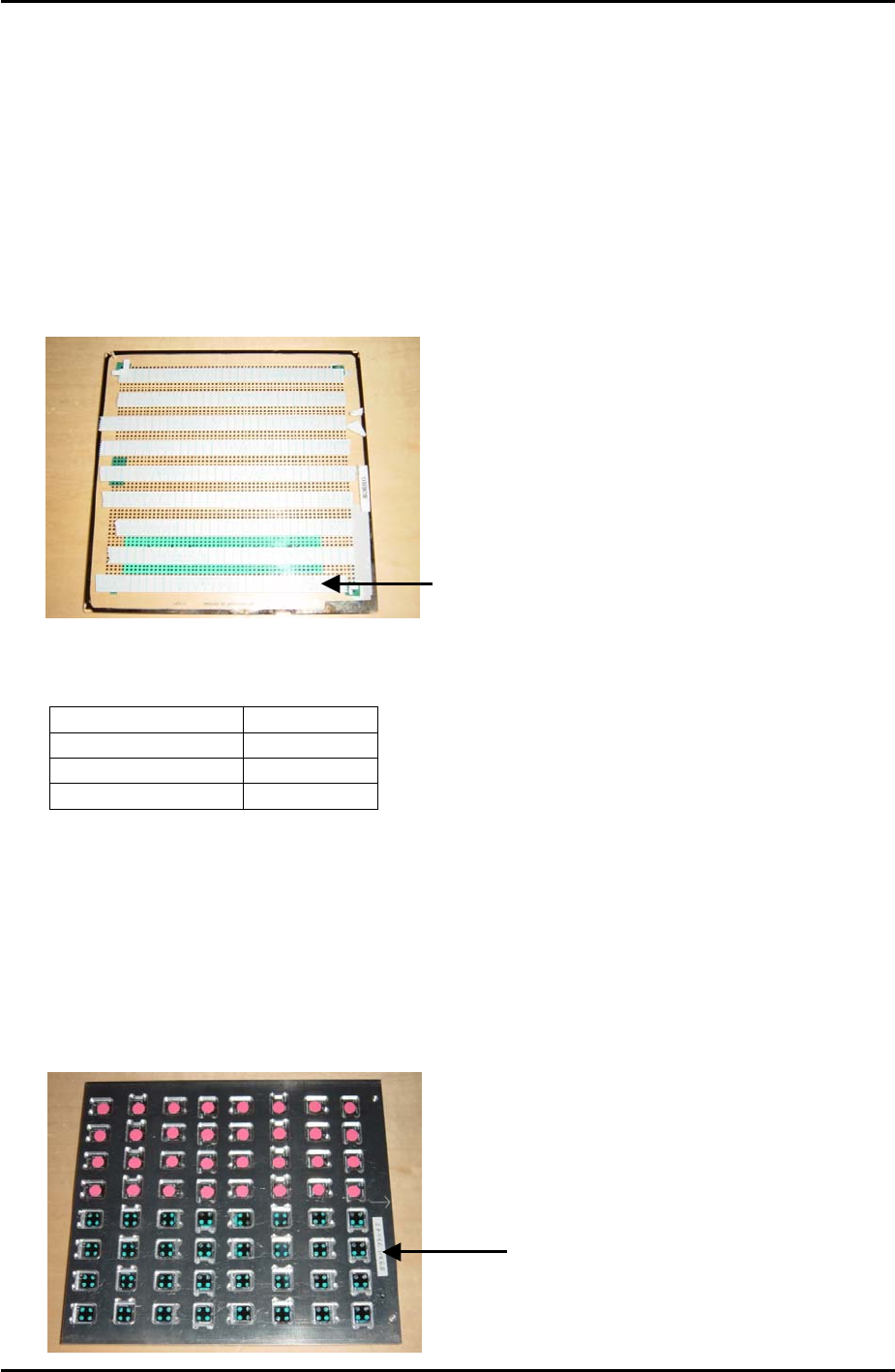
3. Put double sided tape on the board as shown in the photo below:
The tape should cover the first 4
rows of dots at the bottom of the
board, then there is a gap of 3
rows of dots before the next strip
of tape covers 4 rows of dots and
so on.
4. Select [Maintenance A] – [Operation Settings] – and make the following settings:
Operation Mode Production
Production Mode Automatic
Error handling Error Stop
Accel. Rate 1.00
5. Set the conveyor width to 178mm.
6. Set a 7mm diameter nozzle in slot number 1, and make sure that there is a 1.8mm
diameter nozzle and a 15mm diameter nozzle in the nozzle station. The 7mm nozzle is
used for pick up and placement; the other nozzles may be used if cycle steal occurs
before parts placement.
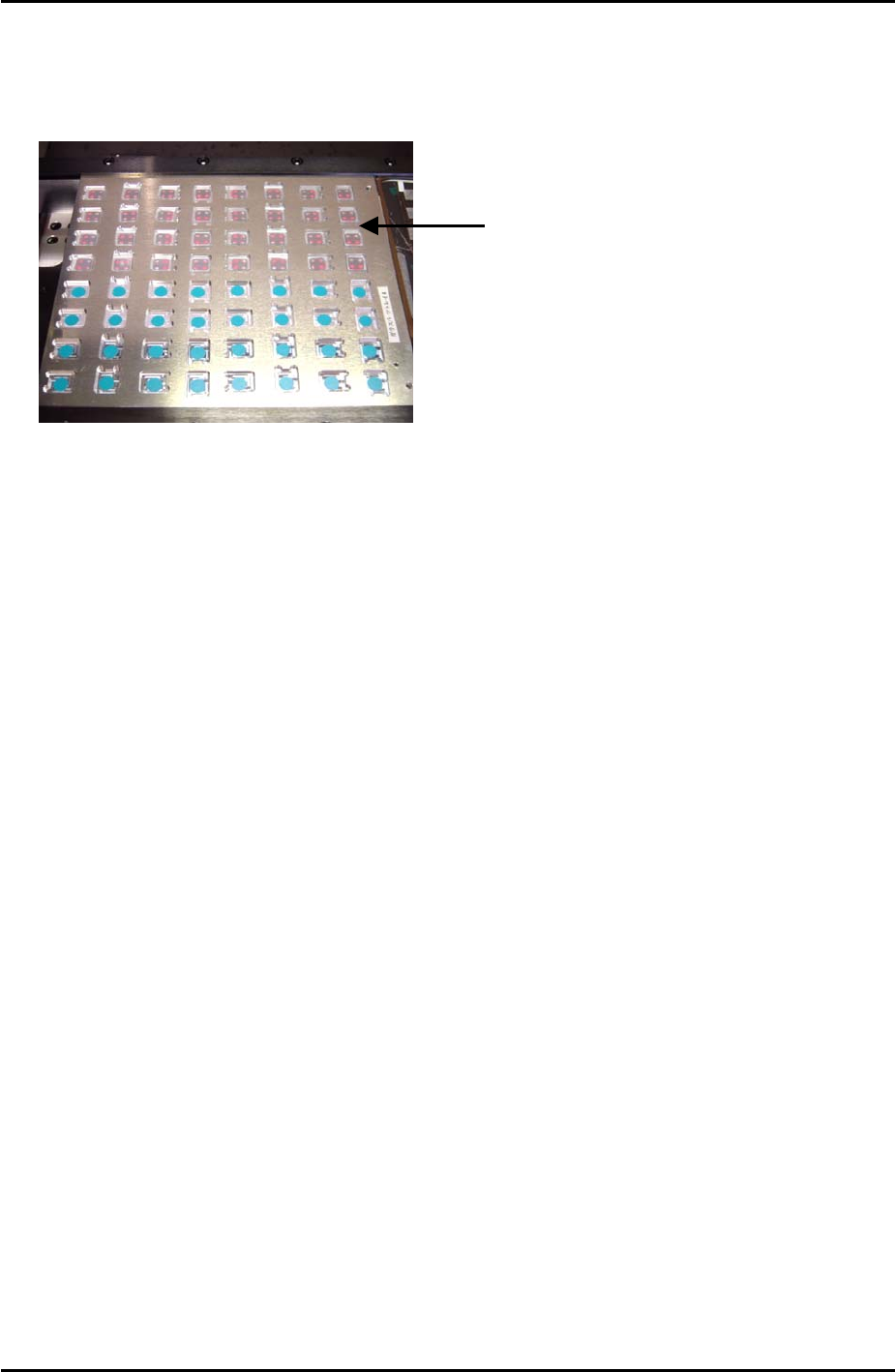
7. Load the glass parts in the front half of the pickup platform jig as shown in the photo
below:
Glass parts are picked
up from the front hal
f
of the pick up jig
Fuji Machine Mfg. Co., Ltd. Okazaki
SMT Equipment Quality Assurance Dept.
7–2 CS Section
FK-9F98-34 XP Type II Series Training Text for Service Engineers
Edition 2.0 XP242E – Chapter 7 Checking Operation and Accuracy Page 3 of 6
8. Load the pick up platform jig and the glass board in the main conveyor.
9. Check for interference and then select [Maintenance C] – [Glass Guage measurement] –
[READY ON] – [Stopper Up] to raise the main stopper. Put the glass board and pick up
platform jig against the stopper as shown in the photo below, then select [Clamp] –
[START] to clamp the main conveyor:
10. Select [Side1] – [Start] – [START] and the machine picks up the parts and places them on
the glass board.
11. When parts placement is completed and a message appears press [START] to carry out
measurement.
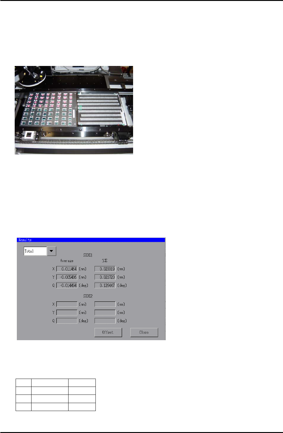
12. When measurement is completed press [OK] and select [Results] to display the results of
the measurement. The following window displays:
13. Select [Offset] – [OK] to save the placement offset.
14. Repeat steps 7 to 13 until the results are within the following tolerance:
Average 3∑
X
+/- 0.010 0.030
Y
+/- 0.010 0.030
Q
+/- 0.200 0.100
Fuji Machine Mfg. Co., Ltd. Okazaki
SMT Equipment Quality Assurance Dept.
7–3 CS Section
FK-9F98-34 XP Type II Series Training Text for Service Engineers
Edition 2.0 XP242E – Chapter 7 Checking Operation and Accuracy Page 4 of 6
Side 2
1. Repeat for the side 2 camera, (select side 2 at step 10) and move the parts to the rear
half of the pickup jig as indicated in the photo below:
Glass parts are picked
up from the rear half o
f
the pick up jig
Fuji Machine Mfg. Co., Ltd. Okazaki
SMT Equipment Quality Assurance Dept.
7–4 CS Section