XP Type II 工程师培训手册 (2.0).pdf.pdf - 第107页
FK-9F98-34 XP T ype II Series T raining T ext for Service Engineers Edition 2.0 XP242E – Chapter 1 Initial Adjustment Page 3 of 8 3. Press [SET] for more than 2 seconds. 4. Press [SET] once (“HYS” appears on the display)…
FK-9F98-34 XP Type II Series Training Text for Service Engineers
Edition 2.0 XP242E – Chapter 1 Initial Adjustment Page 2 of 8
4. Finally confirm that all of the leveling sheets are stable,
and check once again that the leveling is within
tolerance.
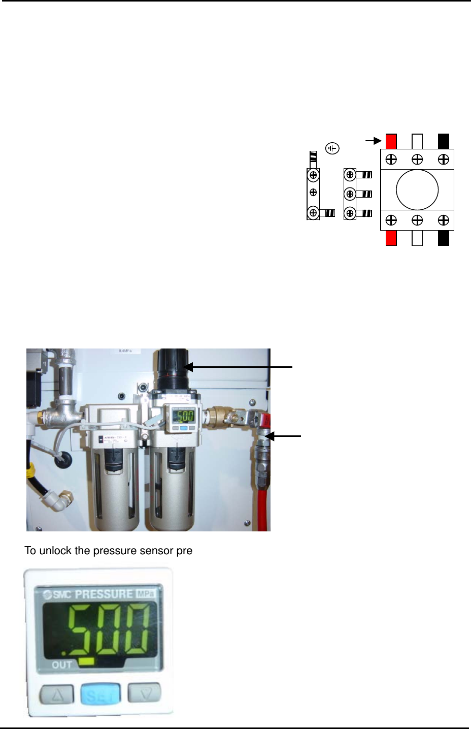
1.2 Power and Air Connection
Power Supply Connection
L2 L3 L1
1. Open the power supply BOX at the lower right hand
side of the machine and pull the power line through the
bottom of the BOX.
Red
2. Connect the ground terminal and the ground wire first.
3. Connect the three wires of the power supply cable to
the three breaker box (KG41B) terminals.
L1: red L2: white L3: black
Air Pressure Setting
1. Connect the hose to the air inlet at the machine rear side.
Air Regulator
Air Inlet
2. To unlock the pressure sensor press [SET] for more than 4 seconds.
Pressure Sensor
Fuji Machine Mfg. Co., Ltd. Okazaki.
SMT Equipment Quality Assurance Dept.
1 – 2 CS Section
FK-9F98-34 XP Type II Series Training Text for Service Engineers
Edition 2.0 XP242E – Chapter 1 Initial Adjustment Page 3 of 8
3. Press [SET] for more than 2 seconds.
4. Press [SET] once (“HYS” appears on the display).
5. Press [SET] once (“no” appears on the display).
6. Press [SET] once (“mAn” appears on the display).
7. Press [SET] once and the current air pressure displays (MPa). Unlock and turn the air
regulator until the pressure reading is 500 MPa. Lock the air regulator.
8. Press [SET] once (“P_1” and “.***” flash alternately).
9. Set the “.***” value to “.400”. This is the setting for the pressure switch, if the air pressure
drops below 400MPa the servo power to the machine will be cut.
10. Press [SET] twice to return to the original display.
11. Finally press and hold [SET] for more than 4 seconds to lock the pressure sensor.
1.3 Lubrication
Apply lubricant to the following areas:
Lubrication point
Daphne Eponex
No.2
Biral T&D
Z-axis ball screw O X
Spline shaft O X
Q-axis helical gear O X
Balls-crew (conveyor) O X
LM rail (conveyor) O X
Conveyor chain X O
Link arm sliding area (lifter plate) O X
Link arm sliding area (cutter) O X
LM rail (cutter) O X
LM rail (MTU) X O
Ball guide (MTU) O X
Ball-screw (MTU) O X
Note: Apply anticorrosion spray to the machine base, brackets, and other metal surfaces, to
prevent rust.
Note: Do not over apply lubricant to the ball screws, helical gears, LM guide rails, or other
parts of the machine that rotate or move at high velocity. Over lubrication may result in the
lubricant being flung around the machine and interfering with the sensors, vision processing,
and other aspects of the machine operation.
Fuji Machine Mfg. Co., Ltd. Okazaki.
SMT Equipment Quality Assurance Dept.
1 – 3 CS Section
FK-9F98-34 XP Type II Series Training Text for Service Engineers
Edition 2.0 XP242E – Chapter 1 Initial Adjustment Page 4 of 8
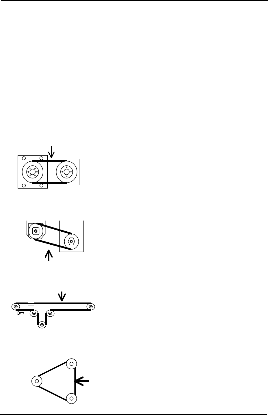
1.4 Belt Tension Measurement
1. Measuring equipment: Tension meter
2. Use the tension meter to check the belt tension of the Y, Z, T and U axes.
3. Press the Emergency Stop button and move each of the axes to the Minus (-) mechanical
stopper.
4. Refer to the following illustrations and check that the belt tension for each axis is within
the target range:
Y-axis measuring point
Tension meter setting
Belt unit amount: 4gf/m Target Frequency
Belt width:15mm 148~166 Hz
Span length:127mm
Z-axis measuring point
Tension meter setting
Belt unit amount: 2.5gf/m Target Frequency
Belt width: 9mm 389~431Hz
Span length: 54mm
U-axis measuring point
Tension meter setting
Belt unit amount: 2.5gf/m Target Frequency
Belt width:9mm 39~43Hz
Span length: 543mm
T-axis measuring point
Tension meter setting
Belt unit amount: 2.5gf/m Target Frequency
Belt width: 15mm 140~154Hz
Span length: 151mm
Motor
Ball screw
Mid pulley
Fuji Machine Mfg. Co., Ltd. Okazaki.
SMT Equipment Quality Assurance Dept.
1 – 4 CS Section