XP Type II 工程师培训手册 (2.0).pdf.pdf - 第73页
FK-9F98-34 XP T ype II Series T raining T ext for Service Engineers Edition 2.0 XP142E – Chapter 6 Proper Dat a Measurement s Page 14 of 30 6.9 Mark Camera Focus 1. Equipment: plate jig (AJPJ – 0060). 2. Clamp the plate …
FK-9F98-34 XP Type II Series Training Text for Service Engineers
Edition 2.0 XP142E – Chapter 6 Proper Data Measurements Page 13 of 30
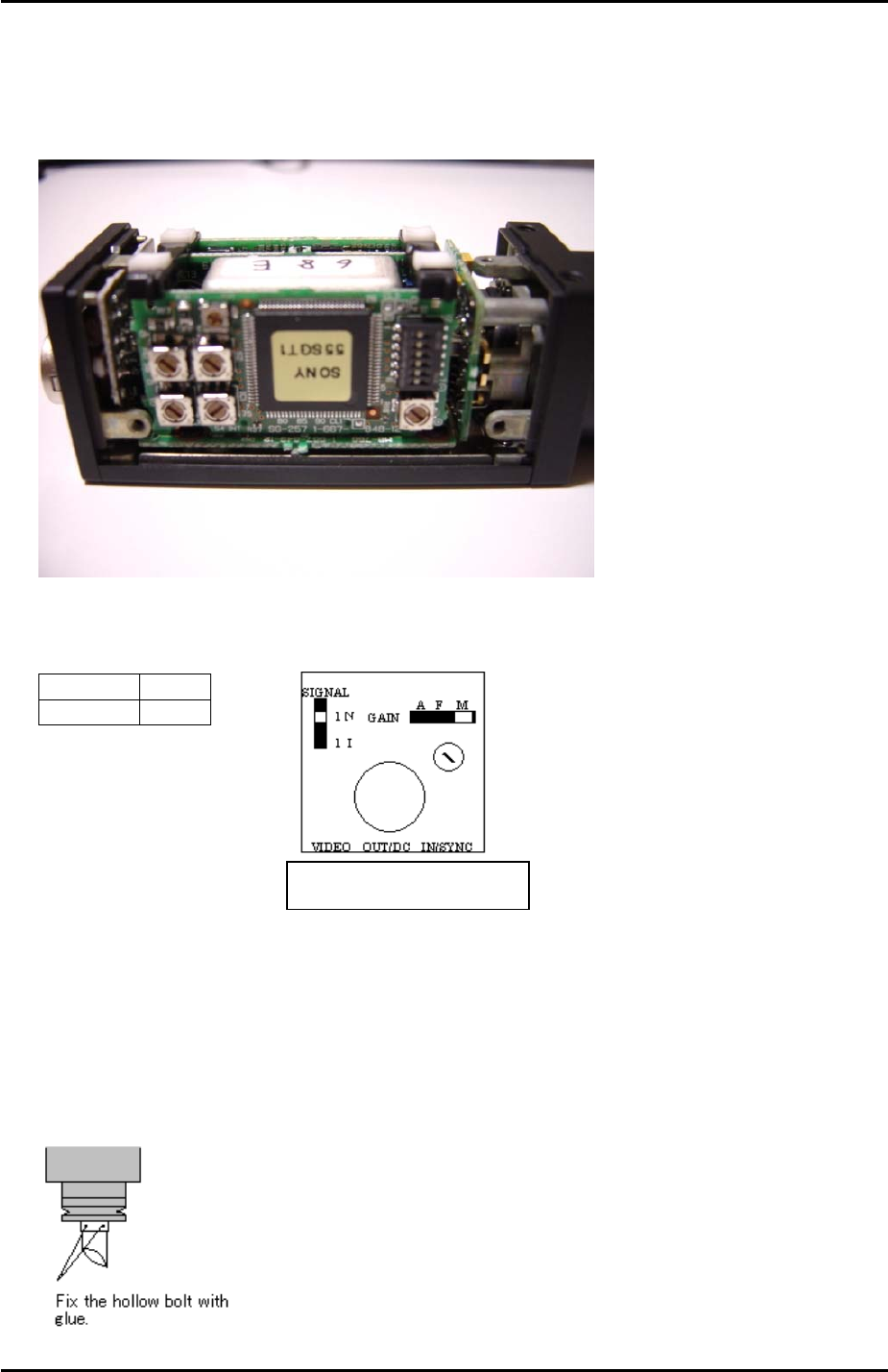
6.8 Mark Camera Setting
1. On a new camera remove the cover and check that the internal settings are as shown in
the following photo:
2. Set the mark camera settings as outlined in the following table and diagram:
Top view of the camera
Signal 1N
Gain M
3. If attaching the mark camera unit to the mark camera installation bracket use 0.5N.m
torque.
4. Ensure that the join where the camera lens unit and camera are connected is reinforced
with adhesive.
5. Ensure that adhesive (Loctite 425) is applied to the hollow bolts that hold the half mirror
in place. Do not over apply adhesive.
The orientation of the half-mirror is
not critical to the mark camera
operation; therefore any orientation
is acceptable.
Fuji Machine Mfg. Co., Ltd. Okazaki
SMT Equipment Quality Assurance Dept.
6 – 13 CS Section
FK-9F98-34 XP Type II Series Training Text for Service Engineers
Edition 2.0 XP142E – Chapter 6 Proper Data Measurements Page 14 of 30
6.9 Mark Camera Focus
1. Equipment: plate jig (AJPJ – 0060).
2. Clamp the plate jig in the main conveyor.
3. Select [Maintenance A] – [Jog] – [Fiducial] – the light comes ON for the mark camera and
the live image is displayed on the screen.
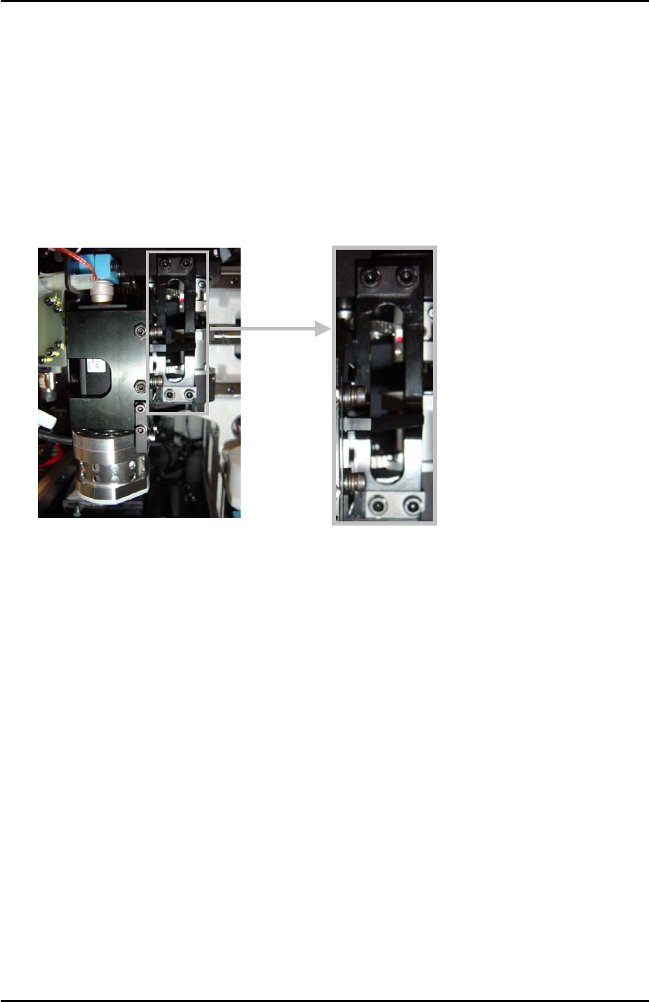
4. Inch the mark camera over the plate jig and set the focus by loosening the 4 mark
camera bracket height adjusting bolts (see photo below), and then sliding the camera up
and down until the optimum focus height is found.
4
3
2
1
5. Finally lock the mark camera bracket height adjusting bolts.
6.10 Mark Camera Brightness
1. Clamp the plate jig in the main conveyor.
2. Place the color sample on top of the plate jig.
3. Select [Maintenance A] – [Jog] – [Fiducial] – the light comes ON for the mark camera and
the live image is displayed on the screen.
4. Inch the mark camera above the color sample disc and touch the image on the screen. A
brightness value will appear.
5. Set the brightness value to 130 +/- 10 by turning the gain adjusting screw on top of the
mark camera.
6. The brightness value will vary slightly at different points on the color sample image,
therefore set the average value to 130.
Fuji Machine Mfg. Co., Ltd. Okazaki
SMT Equipment Quality Assurance Dept.
6 – 14 CS Section
FK-9F98-34 XP Type II Series Training Text for Service Engineers
Edition 2.0 XP142E – Chapter 6 Proper Data Measurements Page 15 of 30
6.11 Mark Camera Resolution Measurement
1. Equipment: mark camera resolution measurement jig (Z3502DEAJ0020).
2. Clamp the resolution jig in the main conveyor. It should be flush with the reference rail,
and the printed surface should be uppermost.
3. Select [Maintenance C] – [Custom Maintenance] – [Fiducial] – the fiducial lamp comes
ON and the mark camera live image is displayed on the screen.
4. Inch the mark camera over the center of the resolution jig.
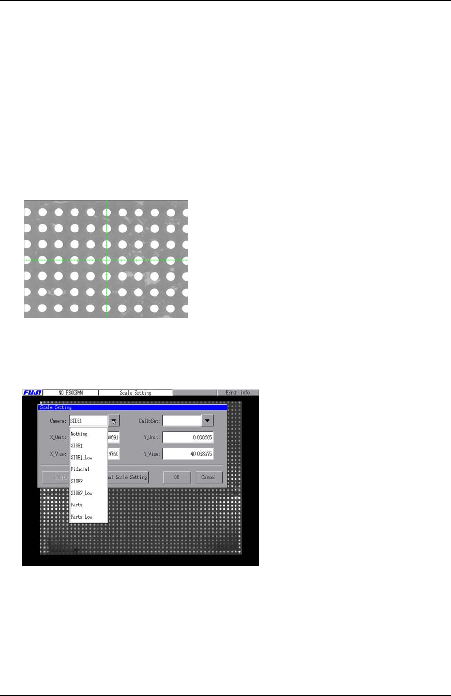
5. Select the cross hairs and set the center of the cross hairs in the center of the resolution
jig center dot.
6. Select [Close] to exit Maintenance Mode and then select [Maintenance A] – [Scale
Setting] and choose [Fiducial] from the drop down list. Select “1.0 [mm] pitch WHITE”
from the [CalibSet] drop down list.
7. Select [Calibration] and answer YES to the question “Set Center?” and the resolution
measurement will proceed.
8. Answer NO to the question “Do you save calibration data to FD?”
9. To the next question “Save Calibration Data?” answer YES.
Fuji Machine Mfg. Co., Ltd. Okazaki
SMT Equipment Quality Assurance Dept.
6 – 15 CS Section