XP Type II 工程师培训手册 (2.0).pdf.pdf - 第15页
FK-9F98-34 XP T ype II Series T raining T ext for Service Engineers Edition 2.0 XP142E – Chapter 1 Initial Adjustment Page 5 of 8 Fuji Machine Mfg. Co., Ltd.Okazaki 1.5 Computer Connection Note: at the time of publicatio…
FK-9F98-34 XP Type II Series Training Text for Service Engineers
Edition 2.0 XP142E – Chapter 1 Initial Adjustment Page 4 of 8
Fuji Machine Mfg. Co., Ltd.Okazaki
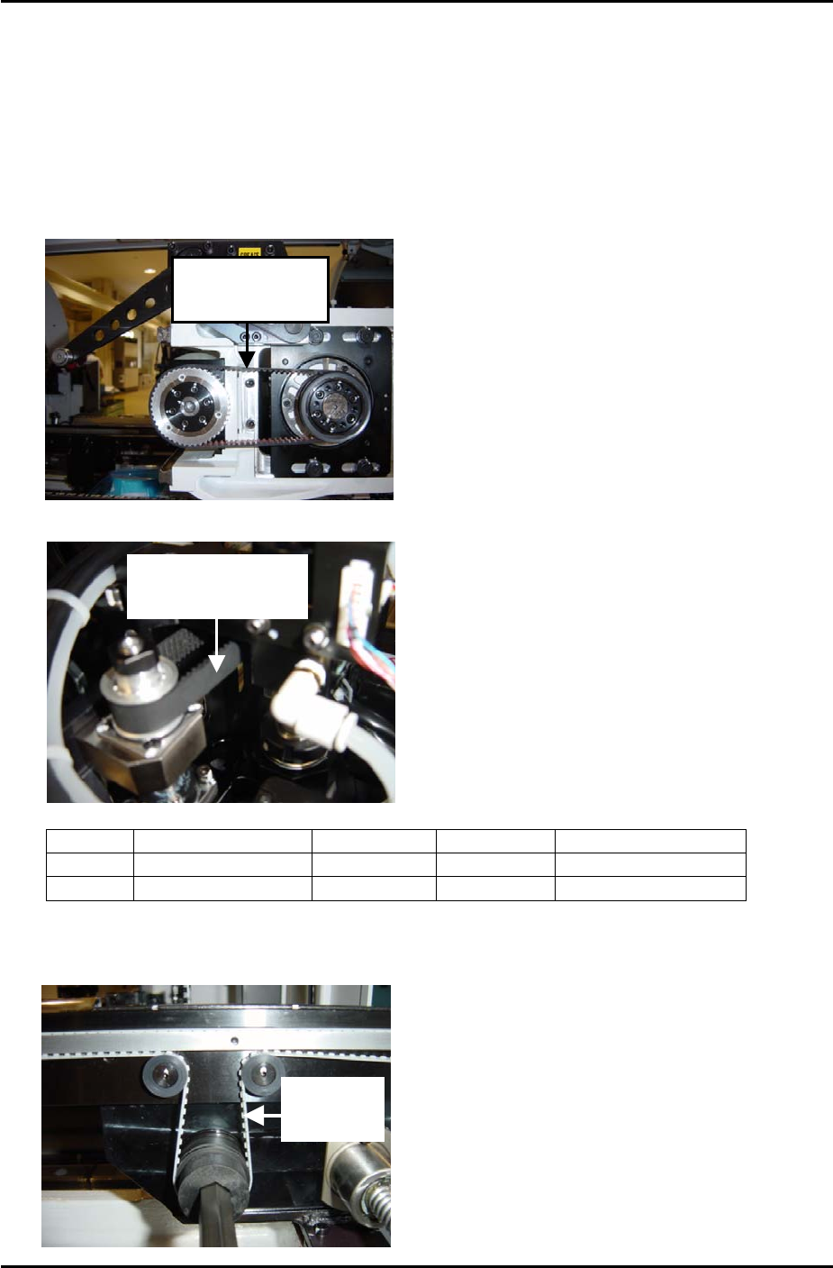
1.4 Belt Tension Measurement
1. Equipment: belt tension meter.
2. Press the emergency stop button to cut the 200-volt power supply to the servos and then
bring the Y and Z axes to the minus mechanical stoppers.
3. Refer to the following illustrations and check that the tension of each belt is within the
appropriate range:
Measure Y-axis
here at side 2
Measure Z-axis
here at side 1
Belt unit weight Belt width Belt span Frequency range
Y axis
0.4 gf/mm 15mm 130mm 145 –163 Hz
Z axis
0.2 gf/mm 8mm 110mm 206 – 228Hz
4. Finally check the tension of the fixed rail and adjustable rail conveyor belts, measure at the
point indicated in the photo below. Tension should be in the range 425 ~ 445 Hz.
Measure
Here
SMT Equipment Quality Assurance Dept.
1 – 4 CS Section
FK-9F98-34 XP Type II Series Training Text for Service Engineers
Edition 2.0 XP142E – Chapter 1 Initial Adjustment Page 5 of 8
Fuji Machine Mfg. Co., Ltd.Okazaki
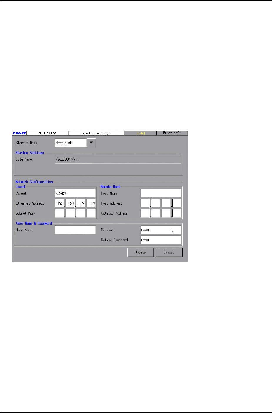
1.5 Computer Connection
Note: at the time of publication of this manual the XP type II machine type is not officially
supported in the MCS/X, F4G or FujiCam host systems. Communication between the XP type
II and these hosts is possible but “machine type” should be set to XP141 or XP241.
Machine Side
1. Connect the LAN cable to the PC.
2. Remove the bottom left cover at the front of the machine, and connect the LAN cable to the
LAN port.
3. Select [Maintenance B] – [Start Up Settings]:
Target: Input the machine nickname.
Ethernet Address: Input the machine IP address.
4. After inputting the “Target” and “Ethernet Address” click on [Update] to save the new
settings and reboot the machine in order for them to take effect.
SMT Equipment Quality Assurance Dept.
1 – 5 CS Section

FK-9F98-34 XP Type II Series Training Text for Service Engineers
Edition 2.0 XP142E – Chapter 1 Initial Adjustment Page 6 of 8
Fuji Machine Mfg. Co., Ltd.Okazaki
MCS/X
1. At the PC select [Start] – [Programs] – [MCSX] – [MCSX].
2. Click on the [File Manager] tab to bring up the "File Exchange" window.
3. To add a line, click on [Add Line], then enter a new line name, and click on [OK].
4. To add a machine, click on [Add M/C]:
Line Name: Choose an available line.
Machine nick n
ame: For example XP241A
Machine t
ype: Input the machine type.
I
P Address: Input an IP address.
5. When finished click on [OK].
F4G
1. At the PC select [Start] – [Programs] – [Windows NT Explorer] – [Winnt] – [System 32]
– [drivers] – [etc] – [hosts] and open the hosts file with notepad, a text file similar to the
one below will then open:
127.0.0.1 localhost
192.168.33.190 italy
192.168.39.2 pascal
192.168.39.10 uk
192.168.33.154 XP241A
2. Make a new entry, and in the first column input the machine's IP address, then a "host
name" in the next column. Close and save the file.
3. Select [Start] – [Programs] – [F4G] – [F4G] – [Line Config] and a text file will open. In
the MC Name column input the same hosts name as that registered in the hosts file, then in
the HOSTNAME column also input the same host name as that registered in the hosts file,
in this case XP241A. Under the MCTYPE column input the machine type, for example
XP241. Close and save the file.
4. At the PC select [Start] – [Programs] – [Windows NT Explorer] – [F4G] – [CC] –
[Passwd] and open the passwd file with notepad, a text file similar to the one below will
then open:
# C/C OS User-ID PassWord
#cc1, OS9, super, user
italy, WINDOWSNT, Administrator,
XP241A, WINDOWSNT, anonymous,
Make a new entry, and in the first column of the new entry input the same host name as that
registered in the hosts file. In the OS column input WINDOWSNT, and in the User-ID
column input, anonymous. Close and save the file.
5. The settings are now complete, restart the computer in order for them to take effect.
6. To confirm that the machine and PC are communicating, enter the F4G Operator Module
and open up the Transmit Engine and then the Transmitter.
SMT Equipment Quality Assurance Dept.
1 – 6 CS Section