XP Type II 工程师培训手册 (2.0).pdf.pdf - 第44页
C C h h a a p p t t e e r r 5 5 P P e e r r i i p p h h e e r r a a l l A A d d j j u u s s t t m m e e n n t t s s
FK-9F98-34 XP Type II Series Training Text for Service Engineers
Edition 2.0 XP142E – Chapter 4 Loader Adjustment Page 12 of 12
4. 10 Conveyor Width and Movement
1. Ensure that the width change can be carried out smoothly, when the conveyor is moved
to its Min. (50mm or less) ~ Max. (356mm or greater) width.
Note: Do not use the conveyor auto width changer, as this is not adjusted yet.
2. Set the entrance of the In-conveyor to 130mm. Check a few points along the conveyor
width from entrance to exit. The difference between the maximum width and minimum
width should be within 0.5mm. If it is out of the tolerance, please contact FUJI.
3. The speed of board loading and the speed of the conveyor width changer are set at FUJI
prior to machine shipment. Changing these speeds is not recommended. However for
your reference the location and function of the conveyor speed controllers are given
below:
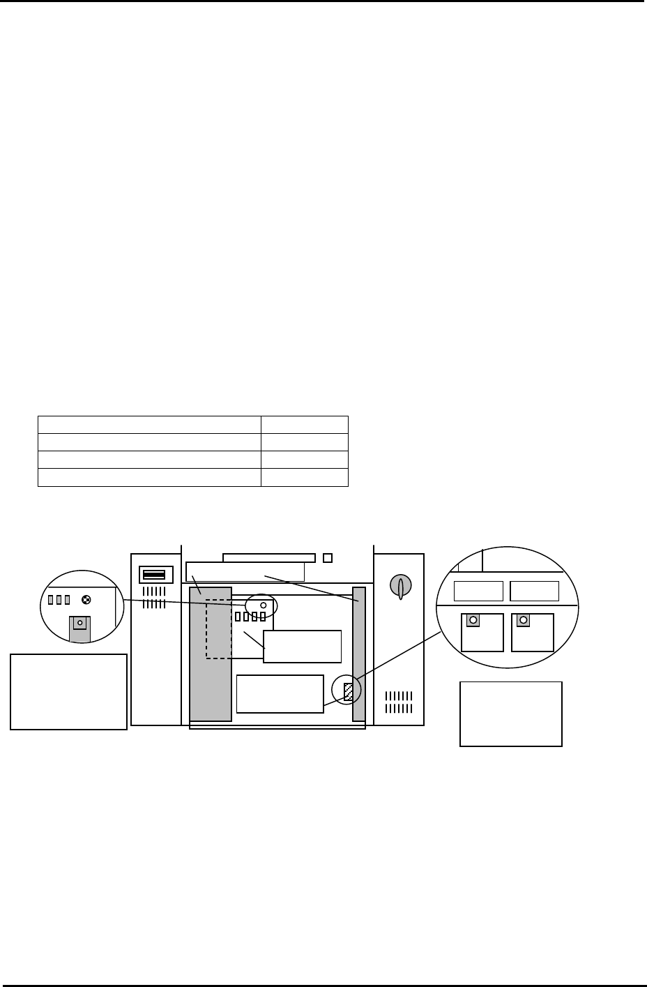
Loading Function Controller
Board Loading (Normal speed) T1VR1
Board Loading (Deceleration) T1SP1
Conveyor width change T1SP2
T1SP1 T1SP2
T1VR1
Main rela
y
board
Speed control
board cover
Electric Box Doo
r
Side1: Rear of the
Electric Box, top
left connector on
the main relay
board.
Side1; Back of
the right door of
the bottom Box.
Fuji Machine Mfg. Co., Ltd. Okazaki.
SMT Equipment Quality Assurance Dept.
4 – 12 CS Section

C
C
h
h
a
a
p
p
t
t
e
e
r
r
5
5
P
P
e
e
r
r
i
i
p
p
h
h
e
e
r
r
a
a
l
l
A
A
d
d
j
j
u
u
s
s
t
t
m
m
e
e
n
n
t
t
s
s
FK-9F98-34 XP Type II Series Training Text for Service Engineers
Edition 2.0 XP142E – Chapter 5 Peripheral Adjustments Page 1 of 14
Chapter 5 – Peripheral Adjustments
5.1 MFU Height and Clamping Adjustment
1. Adjust the MFU air valve speed controllers as described in the following table:
Speed controller location Number of turns from fully closed Function
On cylinder 2 turns from fully closed Unclamp
On air line 3.5 turns from fully closed Clamp
2. Confirm that there is no jolting when clamping and unclamping the MFU. If necessary
make slight adjustments to the speed controllers to achieve smooth clamping and
unclamping.
3. Clamp the MFU.
Warning: the MFU device table is very heavy; please take extreme care to prevent your
finger/hand getting caught when carrying out height or other adjustments on the MFU.
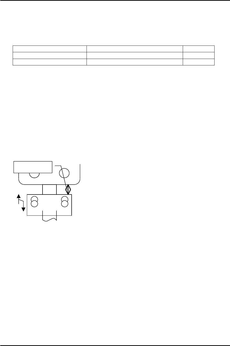
4. Adjust the MFU height adjustment stopper, so that when the MFU is clamped, the gap
between the stopper and the MFU device table underside is approximately 20mm.
Please see the following diagram:
A
pprox. 20mm
Fuji Machine Mfg. Co., Ltd. Okazaki
SMT Equipment Quality Assurance Dept.
5 – 1 CS Section