XP Type II 工程师培训手册 (2.0).pdf.pdf - 第127页
FK-9F98-34 XP T ype II Series T raining T ext for Service Engineers Edition 2.0 XP242E – Chapter 4 Loader Adjustment Page 2 of 12 50 180 180 50 1 10 1 10 80 C B A E D F I H G 6. If the four corners of t he table are not …
FK-9F98-34 XP Type II Series Training Text for Service Engineers
Edition 2.0 XP242E – Chapter 4 Loader Adjustment Page 1 of 12
Chapter 4: Loader Adjustment
4.1 Lifter Plate Flatness
1. Adjust the conveyor to its maximum width (356mm).
2. Select [Maintenance A] – [I/O Check] – [Y028 MainStLifterUp] to raise the main lifter.
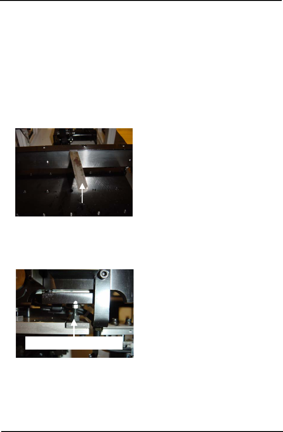
3. Make sure that there is some clearance between the clamper plate and the conveyor rail.
Use a 0.03mm feeler gage as shown in the photo below:
0.03mm feeler gage
Conveyor Rail
Clamper Plate
4. If there is no clearance unlock and screw in the clamper height adjustment bolts:
Clamper height adjustment bolt
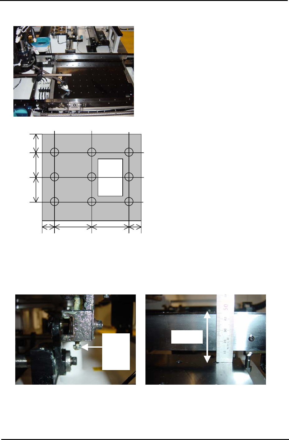
5. Attach a dial gage to the placing head (an extension bar is necessary). Measure the four
corners of the table (points: A, C, G and I). Each value should be 0 indicating that the
table is flat.
Fuji Machine Mfg. Co., Ltd. Okazaki.
SMT Equipment Quality Assurance Dept.
4 – 1 CS Section
FK-9F98-34 XP Type II Series Training Text for Service Engineers
Edition 2.0 XP242E – Chapter 4 Loader Adjustment Page 2 of 12
50 180 180 50
110
110
80
C B A
E D F
I H G
6. If the four corners of the table are not 0, adjust them to 0 using the table height
adjustment bolts. While adjusting the flatness, the height of the table should be set so
that the distance from the back up plate surface to the top of the conveyor rail is 46mm:
Height
A
djust
Bolt
46mm
7. After ensuring the four-corners of the table are flat and the height of the table is correct,
measure the surface of the table at the nine positions shown in the diagram above. Any
deviation should be within 0.10mm. If the values are out of tolerance please contact
FUJI.
Fuji Machine Mfg. Co., Ltd. Okazaki.
SMT Equipment Quality Assurance Dept.
4 – 2 CS Section
FK-9F98-34 XP Type II Series Training Text for Service Engineers
Edition 2.0 XP242E – Chapter 4 Loader Adjustment Page 3 of 12
4.2 Board Clamper
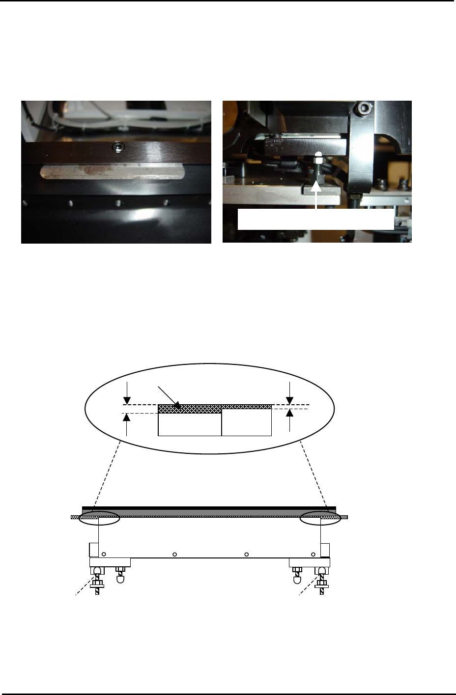
1. Use the clamper height adjustment bolts to set the height of the clamper plate so that
there is a gap of 0.03mm between the top of the clamper plate and the conveyor rail.
0.03mm feeler gage
Clamper height adjustment bolt
2. Lower the lifter plate.
3. Adjust the position of the stoppers so that the lifter plate rests 0.5mm below the top
surface of the conveyor belt.
4. Refer to the diagram below and adjust the stoppers for both the fixed and adjustable rails:
Lifter Plate
Conveyor
Belt
0.5mm
1.0mm
Stopper Stopper
Fuji Machine Mfg. Co., Ltd. Okazaki.
SMT Equipment Quality Assurance Dept.
4 – 3 CS Section