XP Type II 工程师培训手册 (2.0).pdf.pdf - 第83页
FK-9F98-34 XP T ype II Series T raining T ext for Service Engineers Edition 2.0 XP142E – Chapter 6 Proper Dat a Measurement s Page 24 of 30 6.20 Feeder Indexing 1. Equipment: feeder indexing lever height adjustment jig (…
FK-9F98-34 XP Type II Series Training Text for Service Engineers
Edition 2.0 XP142E – Chapter 6 Proper Data Measurements Page 23 of 30
6.19 Pickup Height
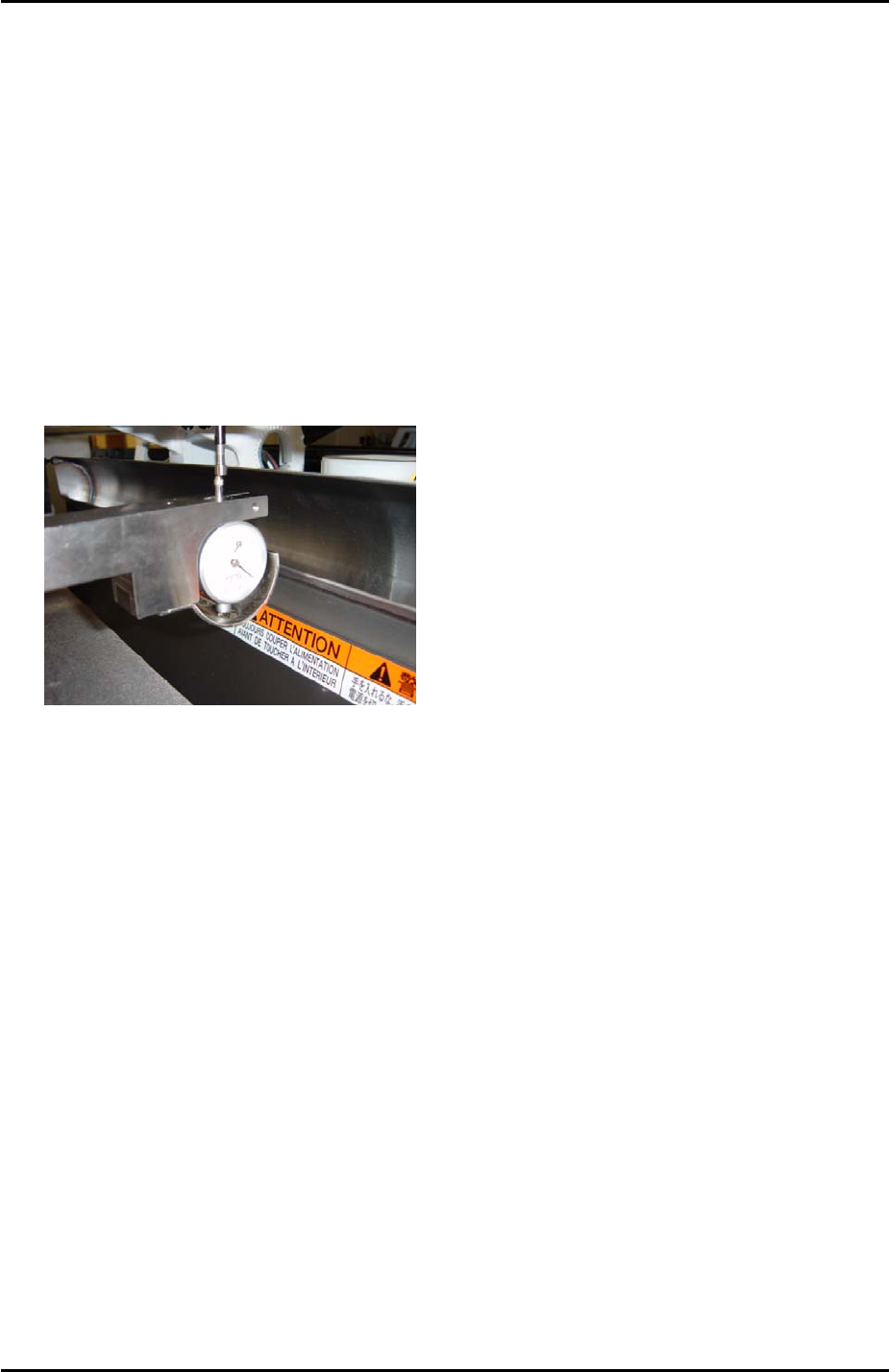
1. Equipment: pick up height measurement jig with dial gage (0.005mm). (Z9064AVJ5540).
Nozzle Jig (A5706ASEAJ8100).
2. Place the pick up height measurement jig in slot 25 of the side1 MFU.
3. Remove all nozzles and insert the nozzle jig in nozzle slot no.1.
4. Bring the R axis to 0 and align the Q axis pusher above the nozzle no.1 piston.
5. Bring the nozzle jig above the pick up height measurement jig dial gage and descend the
Z axis until the dial gage indicates a pick up height of 0.650mm (here the dial gage will be
0). Record the Z-axis counter value at this point.
6. Repeat the procedure for all nozzle slots 1 ~ 12 and record the counter values.
7. Subtract 0.25mm (-0.25mm) from each of the counter values recorded in step 6.
8. Input the counter value for nozzle number 1 at [Maintenance C] – [Proper Data Editor] –
[Machine Origin] – [Z_Stage1 Surface].
9. Now it is necessary to input an offset for all the remaining nozzles.
10. To calculate the offset for nozzle number 2 subtract the nozzle number 2 counter value
from the nozzle number 1 counter value. Input the resulting value in [Maintenance C] –
[Proper Data Editor] – [PICKUP_OFFSET] – [Z_Nzl2PickupOfst].
11. Repeat this procedure to input offsets for the remaining nozzles 3 ~ 12.
Side 2
1. Repeat the procedure for the side2 [Z_Stage2 Surface].
Fuji Machine Mfg. Co., Ltd. Okazaki
SMT Equipment Quality Assurance Dept.
6 – 23 CS Section
FK-9F98-34 XP Type II Series Training Text for Service Engineers
Edition 2.0 XP142E – Chapter 6 Proper Data Measurements Page 24 of 30
6.20 Feeder Indexing
1. Equipment: feeder indexing lever height adjustment jig (Z9913AWPJ9310).
2. The following procedure is the same for both sides of the machine.
Feeder indexing lever height
1. Set the feeder indexing lever height adjustment jig at D25.
3. Return the F and G cams to their upper resting position (the origin position where the F
and G counter values are 0).
4. Bring the feeder indexing lever above the height adjustment jig.
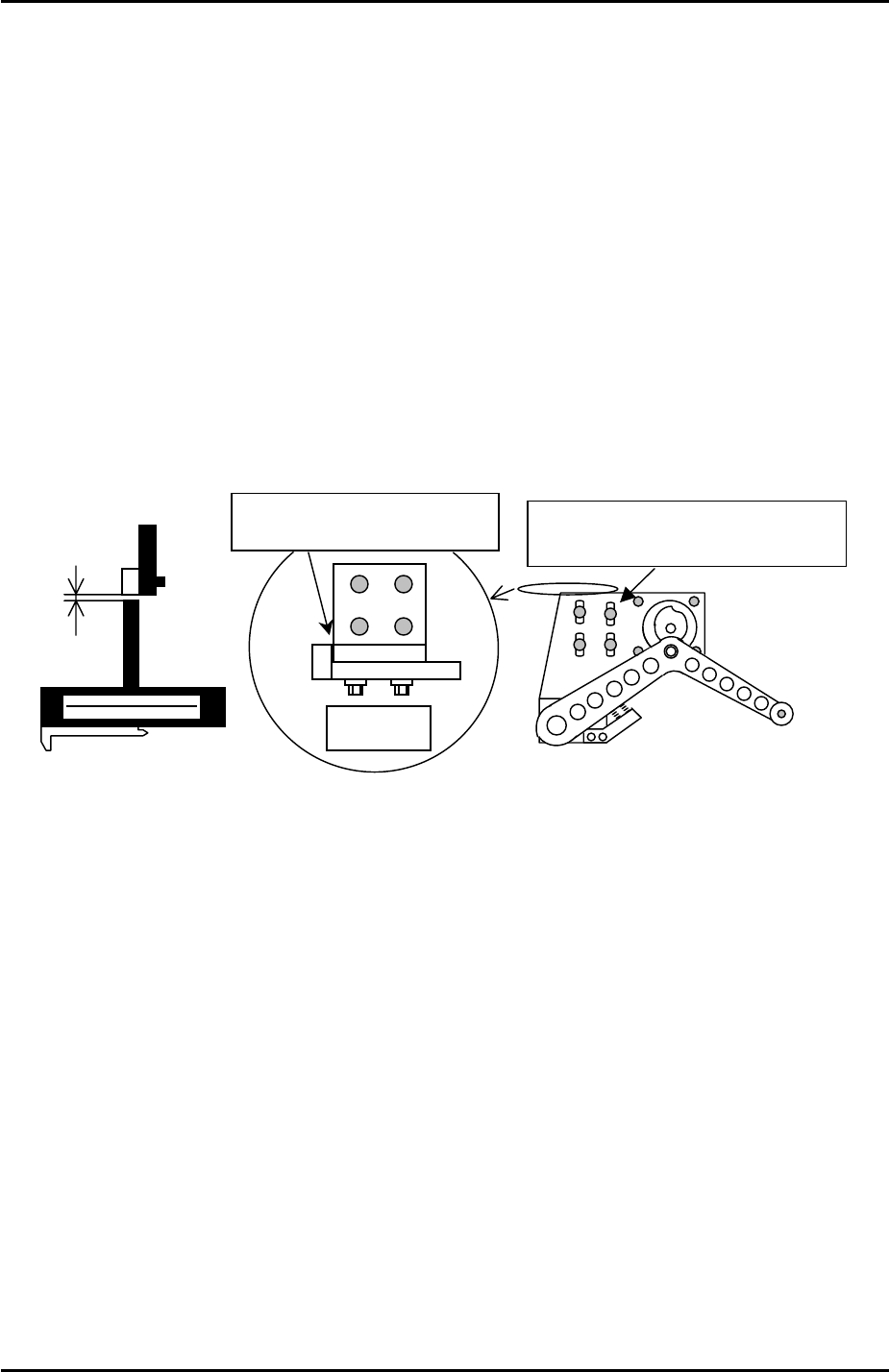
5. Adjust the position of the feeder indexing lever bracket so that the clearance between the
lever and the jig is 0.5mm. Use a feeler gage to set the clearance. Refer to the diagram
below:
0.5mm
A
djust the feeder indexing lever
installation BKT by using these slots.
Top view
(Z9913AWPJ9310)
Make sure these two surfaces
are in contact.
Feeder indexing lever X and Y position
1. Prepare two feeders and set them in D19 and D21 (side2 D79 and D81).
2. Select [Program] – [Editor] – [Part] – and select any part data file.
3. Select [Part Type Edit] – [Template] – and make sure the servo power is ON.
4. Specify [Slot] number 20 and then select [Manual Pickup] – [START] to move the head
and the indexing lever to D20.
5. Press the emergency stop button to cut the 200v power supply to the servos.
6. Push the placing head out of the way along the Y-axis but do not change the position of
the X-axis.
7. Manually descend the feeder indexing lever between the two feeders in slots D19 and
D21.
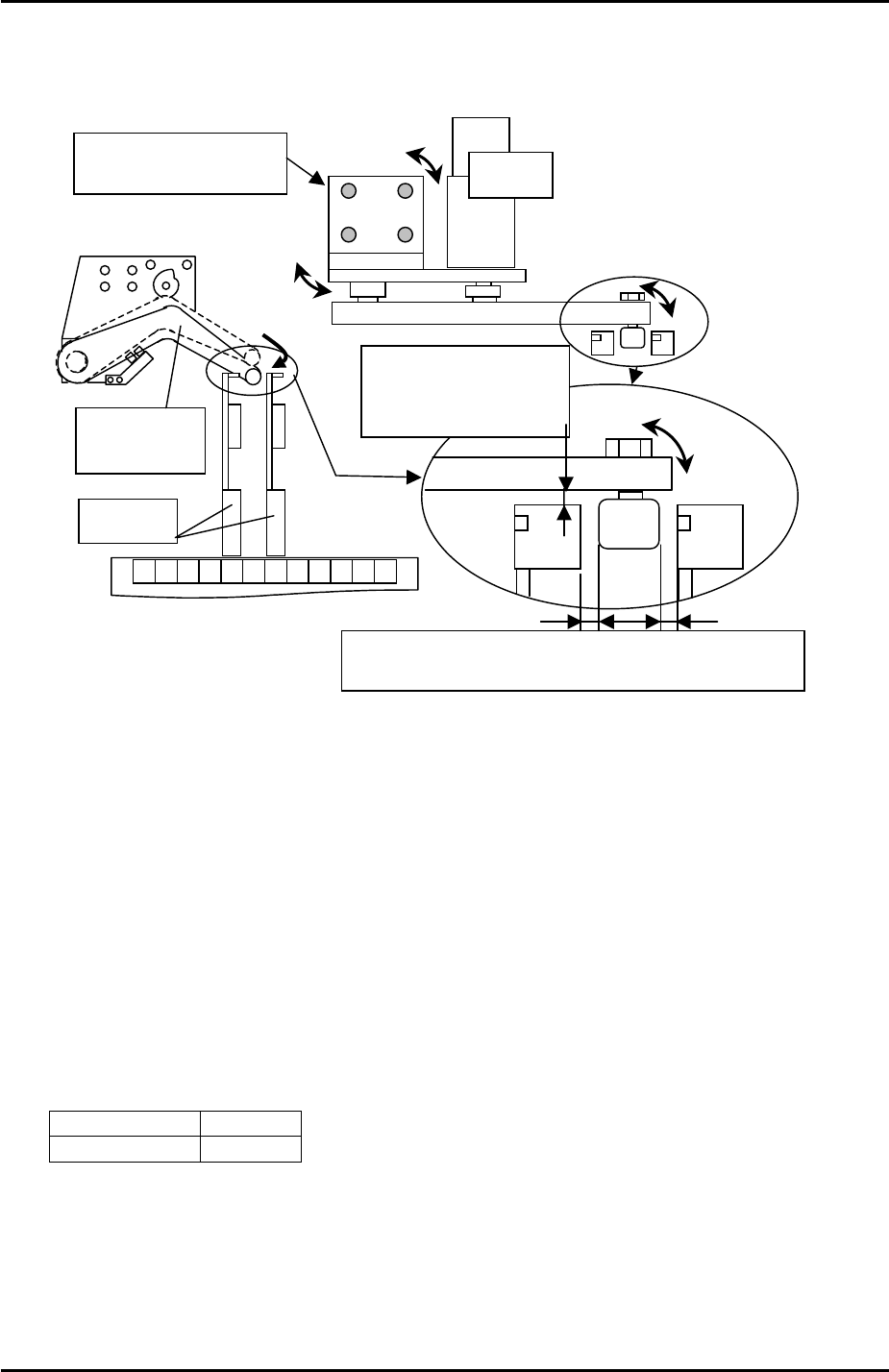
8. At this position the clearance between the tape feeder indexing arm and the XP indexing
lever should be 0.5 to 1.0mm in the Y direction. Refer to the diagram below and adjust if
necessary.
Fuji Machine Mfg. Co., Ltd. Okazaki
SMT Equipment Quality Assurance Dept.
6 – 24 CS Section
FK-9F98-34 XP Type II Series Training Text for Service Engineers
Edition 2.0 XP142E – Chapter 6 Proper Data Measurements Page 25 of 30
9. The position of the XP indexing lever in the X direction should be such that when the
indexing lever is pressed down it is in the center of the two feeders on either side. Refer
to the diagram below and adjust if necessary.
19 21 20 22 18
Feeder
Feeder
index lever
The clearance between
lever and feeder:
0.5mm~1.0mm
Motor
A
djust the motor BKT
for positioning
Adjust to have even clearance between the cam followe
r
and feeder when lowerin
g
the index lever.
10. After any adjustments confirm that the feeder indexing lever height is still 0.5mm (see the
first part of 6.17 “feeder indexing lever height”).
11. Finally select [Maintenance C] – [Proper Data Editor] – [Machine Origin] – and confirm
that the value entered for [F_DownPoint] and [G_DownPoint] is –8.5mm.
6.21 Retract Position
1. The retract position ensures the placing head is not in a position that would cause
interference when clamping or unclamping an MFU from the machine.
2. Select [Maintenance C] – [Proper Data Editor] – [Machine Origin] – and check that the
following proper data is input:
X_Table Org 5mm
Y_Table Org 400mm
Fuji Machine Mfg. Co., Ltd. Okazaki
SMT Equipment Quality Assurance Dept.
6 – 25 CS Section