XP Type II 工程师培训手册 (2.0).pdf.pdf - 第81页
FK-9F98-34 XP T ype II Series T raining T ext for Service Engineers Edition 2.0 XP142E – Chapter 6 Proper Dat a Measurement s Page 22 of 30 6.18 MFU Pickup Position 1. Equipment: pickup position measurement jig. 2. Attac…
FK-9F98-34 XP Type II Series Training Text for Service Engineers
Edition 2.0 XP142E – Chapter 6 Proper Data Measurements Page 21 of 30
6.17 Measuring the R-axis Offset
1. Insert 1.3mm nozzles in all 12 nozzle positions on the revolver.
2. Select [Production] – [Nozzle Editor] – and set all nozzle entries to 1.3mm.
3. Inch the Y-axis to the “PrismFront” position.
4. Select [Maintenance A] – [Jog] – [Side1] to activate the side 1 prism light source and
display the parts camera live image.
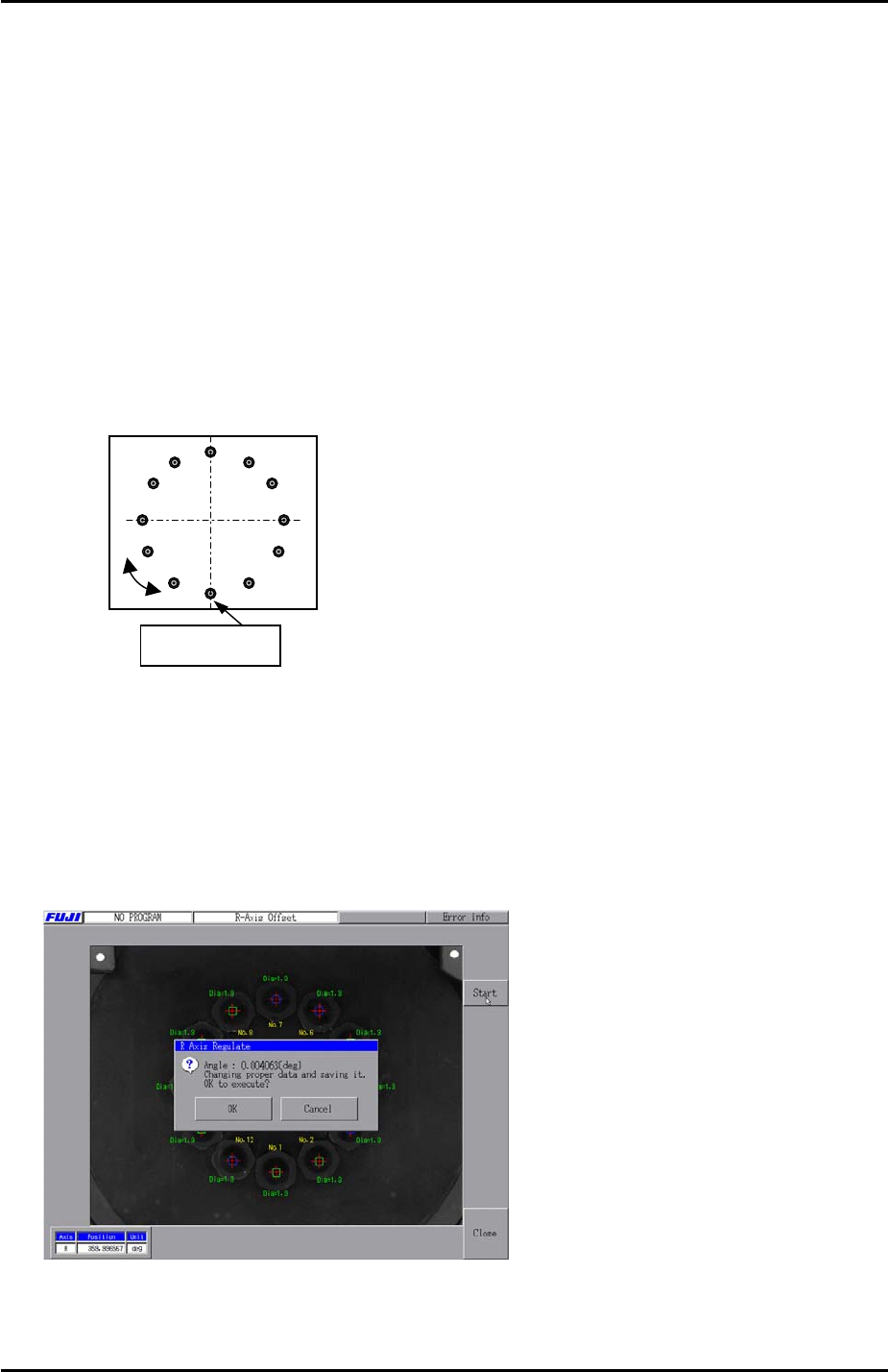
5. Bring nozzle no.1 to the front of the machine and display the cross hairs.
6. Rotate the R axis until the vertical cross hair is aligned with nozzles 1 and 7, and the
horizontal cross hair is aligned with nozzles 4 and 10.
No.7
No.10 No.4
Nozzle No. 1
7. With the R axis in this position refer to chapter 2.5 “Setting the axis origins” and set the Q
axis so that the pusher is against the nozzle number 1 air blow pin.
8. Select [Maintenance C] – [Stroke Zero Set] and select the R and Q axes then press [Set
the Origin] to set the origin for both axes.
9. Select [Maintenance C] – [R axis offset] – [Start] – [START] to measure the R axis offset.
After the calibration is complete press [OK] to save the results.
10. Select [Maintenance C] – [Proper Data Editor] – [Servo Ofst] – [Target Ofst_R] and
confirm that the results of the measurement have been saved in proper data.
Fuji Machine Mfg. Co., Ltd. Okazaki
SMT Equipment Quality Assurance Dept.
6 – 21 CS Section
FK-9F98-34 XP Type II Series Training Text for Service Engineers
Edition 2.0 XP142E – Chapter 6 Proper Data Measurements Page 22 of 30
6.18 MFU Pickup Position
1. Equipment: pickup position measurement jig.
2. Attach the MFUs to side1 and side2.
3. Mount the pick up position measurement jig at D25 on side1.
4. Bring the R axis counter to 0 so that the nozzle no.1 piston comes to the front of the
machine.
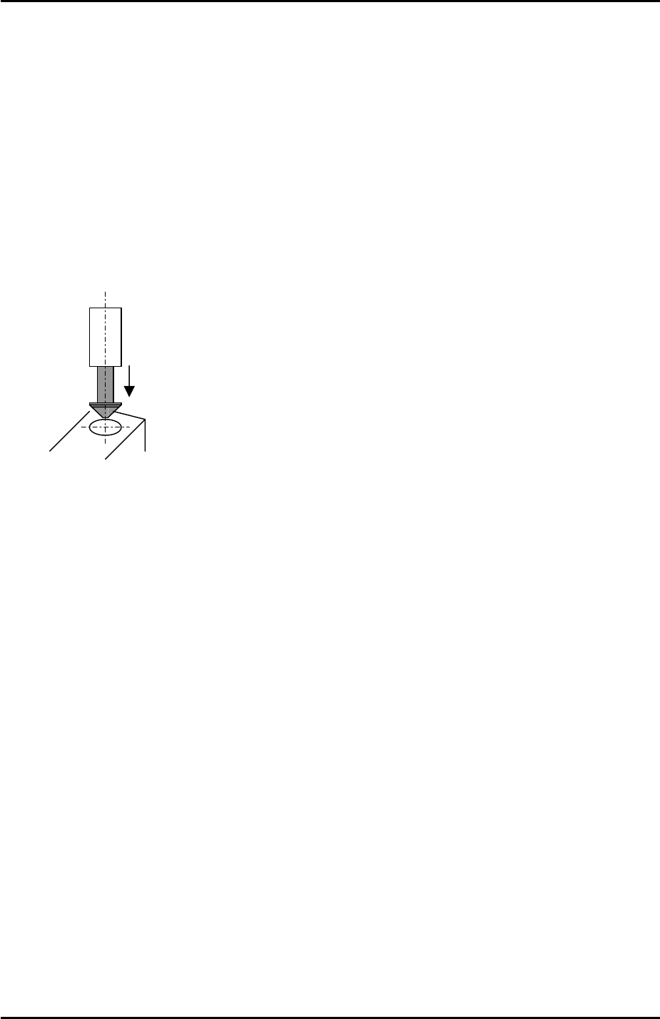
5. Insert a 0.4mm nozzle in the nozzle no.1 piston.
6. Align the 0.4mm nozzle directly above the circular mark on the pick up position
measurement jig.
7. Select [Maintenance C] – [Proper Data Editor] – [Machine Origin] – [X_stage1org] and
[Y_stage1org] – [Direct Servo Input] to save the current X and Y-axis counter values to
proper data.
8. Bring the R axis counter value to 180 degrees and repeat the procedure for the side 2
MFU pick up position [X_stage2org] and [Y_stage2org].
Fuji Machine Mfg. Co., Ltd. Okazaki
SMT Equipment Quality Assurance Dept.
6 – 22 CS Section
FK-9F98-34 XP Type II Series Training Text for Service Engineers
Edition 2.0 XP142E – Chapter 6 Proper Data Measurements Page 23 of 30
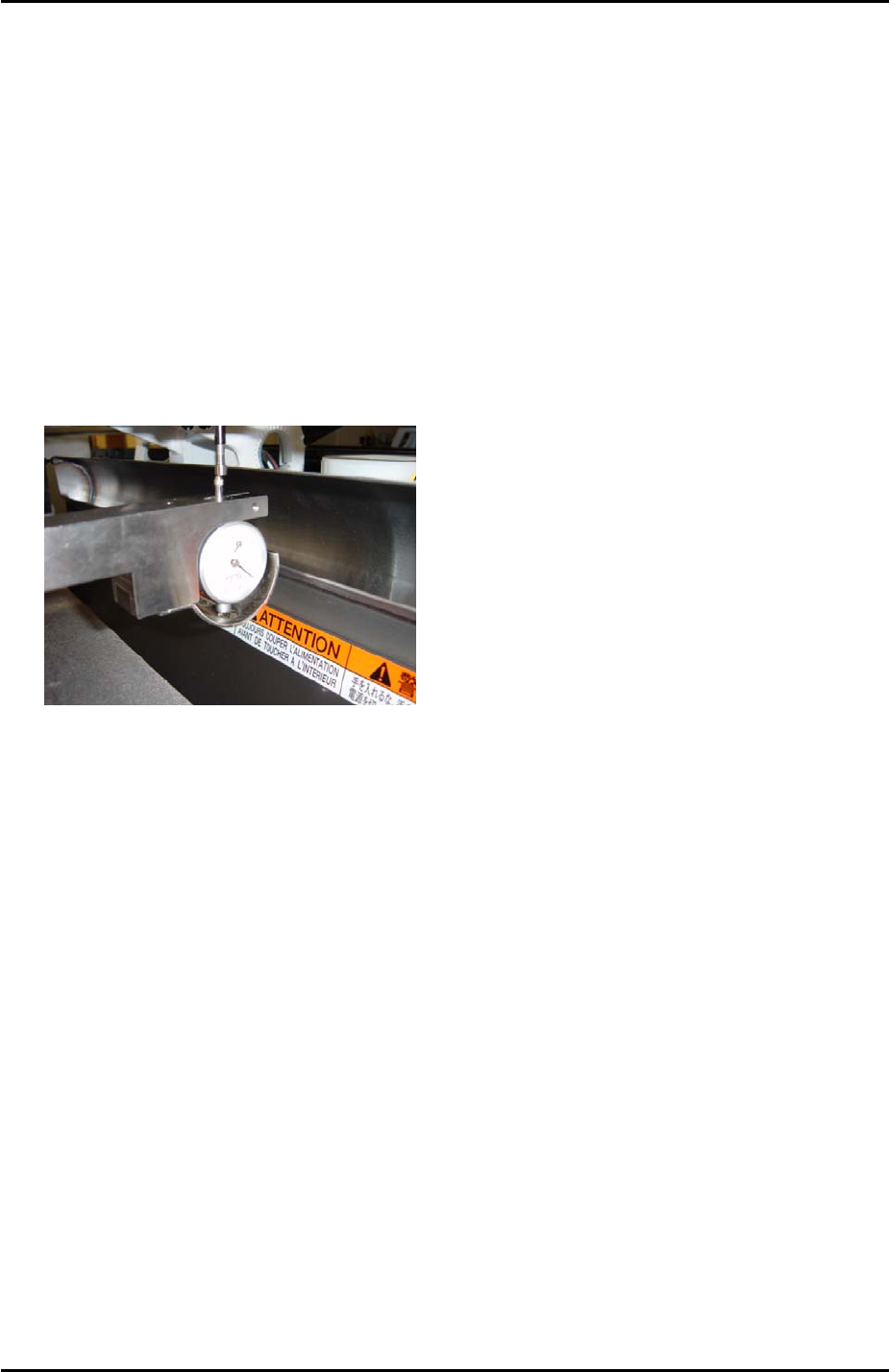
6.19 Pickup Height
1. Equipment: pick up height measurement jig with dial gage (0.005mm). (Z9064AVJ5540).
Nozzle Jig (A5706ASEAJ8100).
2. Place the pick up height measurement jig in slot 25 of the side1 MFU.
3. Remove all nozzles and insert the nozzle jig in nozzle slot no.1.
4. Bring the R axis to 0 and align the Q axis pusher above the nozzle no.1 piston.
5. Bring the nozzle jig above the pick up height measurement jig dial gage and descend the
Z axis until the dial gage indicates a pick up height of 0.650mm (here the dial gage will be
0). Record the Z-axis counter value at this point.
6. Repeat the procedure for all nozzle slots 1 ~ 12 and record the counter values.
7. Subtract 0.25mm (-0.25mm) from each of the counter values recorded in step 6.
8. Input the counter value for nozzle number 1 at [Maintenance C] – [Proper Data Editor] –
[Machine Origin] – [Z_Stage1 Surface].
9. Now it is necessary to input an offset for all the remaining nozzles.
10. To calculate the offset for nozzle number 2 subtract the nozzle number 2 counter value
from the nozzle number 1 counter value. Input the resulting value in [Maintenance C] –
[Proper Data Editor] – [PICKUP_OFFSET] – [Z_Nzl2PickupOfst].
11. Repeat this procedure to input offsets for the remaining nozzles 3 ~ 12.
Side 2
1. Repeat the procedure for the side2 [Z_Stage2 Surface].
Fuji Machine Mfg. Co., Ltd. Okazaki
SMT Equipment Quality Assurance Dept.
6 – 23 CS Section