XP Type II 工程师培训手册 (2.0).pdf.pdf - 第240页
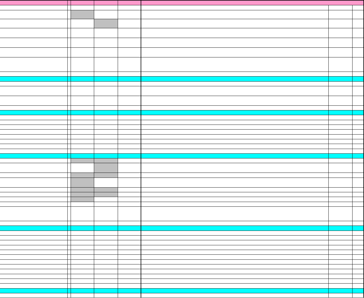
XP Proper Data ListType-II vol.3 Issue Date:2003/6/17 Item XP142 X P242 Input Rang e Explanation Editing Reboot __WaitNextMcOnDelayTimer = 00 0 ~ 300 Sets the delay timer (sec) for waiting for signal from next machine. U…
XP Proper Data ListType-II vol.3
Issue Date:2003/6/17
Item XP142
X
P242 Input Rang
e
Explanation
Editing
Reboot
__AutoConvWidth = 00
0~1
Enables the conveyor width change function at the start of automatic operation. 0:OFF, 1:ON.
User Can Edit
__PlaceUpDelayTimer = 010
0~100
S
etting
f
or the time delay
(
msec
)
f
rom the moment the vacuum break sensor switches o
ff
until the time the Z-axis is
raised.
User Cannot Edit
__DisposePosAutoSW = 00
0~1
S
peci
f
ies automatic sorting o
f
N
G
parts
(
to the box and tray
)
on the XP-142E. 0:Re
f
ers to the part data setting,
1:Automatic sorting.
User Can Edit
__NotFeederPrecedenceAction = 00
0~1
S
e
tti
ng
f
or
f
ee
d
er a
d
vance movemen
t
w
hil
e
th
e
XP
-
242E
i
s c
h
ang
i
ng
t
rays.
0
:
Ad
vance movemen
t
,
1
:
N
o
advance movement.
User Can Edit
__FMarkReadBeforePickUp = 00
0~1
S
e
tti
ng
f
or per
f
orm
i
ng p
i
c
k
-up
i
n a
d
vance, w
hil
e rea
di
ng
fid
uc
i
a
l
mar
k
s.
0
:
Ad
vance p
i
c
k
-up,
1
:
N
o a
d
vance
pick-up.
User Can Edit
__LoggingPort = 00
0
,
8000~8999 Specifies the UDP communication port number
User Can Edit
__CCIMFTemplateMode = 00
0~1
S
e
tti
ng
f
or respon
di
ng w
h
en
t
emp
l
a
t
e
d
a
t
a
i
s no
t
f
oun
d
i
n
th
e pro
d
uc
ti
on program
(
rec
i
pe
)
an
d
v
i
s
i
on
t
ype
18 is specified in part data. Either an error occurs during data check, or the template data is retrieved
from the template file (.TPL). 0:Error, 1:Retrieve from template file.
User Can Edit
__BrightCheckErrorMode = 00
0~1 Specifies whether or not to terminate production when a nozzle brightness measurement error occurs.
User Can Edit
__________VISION__________
_
=
__FiducialMarkImperfect = 00
0~1 Set whether partial circle fiducial marks are supported or not. 0: Not supported. 1: Supported.
User Can Edit
○
__FiducialMeasureFailRatio = 00
0~100
I
n or
d
er
t
o ena
bl
e
th
e measure see
k
li
ne
f
a
il
ure ra
ti
o
(%)
se
tti
ng.
Th
e program mus
t
b
e rerea
d
an
d
compiled.
User Can Edit
__BoardSkipMarkBrightnessLevel = 00
0~255
S
e
t
th
e
b
r
i
g
ht
ness
l
eve
l
rea
di
ng
b
oar
d
s
ki
p mar
k
s.
V
a
l
ues
f
rom
1
t
o
255
are va
lid
.
If
a va
l
ue o
f
0
or
l
ower,
or 256 or higher is specified, the default value of 128 will be used.
User Can Edit
__LookUpTableOf
f
= 00
0~1 Enables the "_LookUpTable" item for vision offset. 0: Enabled, 1: Disabled.
User Can Edit
______PARTS_CAMERA_UNIT___
_
=
__Side1Unit
X
= 3000 3000
None Sets the side 1 standard height unit X position.
Calibration Data
__Side1Unit
Y
= 3000 3000
None Sets the side 1 standard height unit Y position.
Calibration Data
__Side1UnitX_Lo
w
= 3000 3000
None Sets the side 1 low height unit X position.
Calibration Data
__Side1UnitY_Lo
w
= 3000 3000
None Sets the side 1 low height unit Y position.
Calibration Data
__Side2Unit
X
= 3000 3000
None Sets the side 2 standard height unit X position.
Calibration Data
__Side2Unit
Y
= 3000 3000
None Sets the side 2 standard height unit Y position.
Calibration Data
__Side2UnitX_Lo
w
= 3000 3000
None Sets the side 2 low height unit X position.
Calibration Data
__Side2UnitY_Lo
w
= 3000 3000
None Sets the side 2 low height unit Y position.
Calibration Data
________MACHINE_TYPE_2____
_
=
__MachineParameter1 = 00
0~1 Custom specification setting. (Not used.) 0:Standard, 1:Custom.
User Cannot Edit
○
__StageModeSW = 00
0~2
St
age mo
d
e
(AA
mo
d
e
)
f
unc
ti
on se
tti
ng.
0
:
St
an
d
ar
d
mac
hi
nes,
1
,
2
:
St
an
d
ar
d
s
t
age c
h
ange mo
d
e
machines.
User Cannot Edit
○
__RemoverType = 00
0~1 Specifies the tray unloading remover type (Not used.) 0:Conventional type, 1:New type.
User Cannot Edit
__FiducialLampType = 01
0~1
M
ar
k
camera se
tti
ng.
0
:
M
ac
hi
nes o
th
er
th
an
th
ose
i
n
di
ca
t
e
d
b
y se
tti
ng
"1"
b
e
l
ow,
1
:mac
hi
nes re
t
ro
fitt
e
d
with new type infrared mark cameras.
User Cannot Edit
○
__TrayRetractChec
k
= 00
0~1 Enables/disables the tray entry check function. (Not used.) 0:Disabled, 1:Enabled.
User Cannot Edit
__TrayUnitType = 00
0~1 Set whether an XP242E supports tray units or not. 0:Unsupported, 1:Supported.
User Cannot Edit
○
__UseMicroTray = 00
0~1 Set whether high precision microtrays are used or not. 0:Not used, 1:Used.
User Cannot Edit
__SetDetectCensorSW = 11
0~1 Set whether the tape leaf sensor is used or not. 0:Unsupported, 1:Tape leaf W sensor.
User Cannot Edit
○
__EjectPanelUncondition = 00
0~2
S
e
t
th
e mac
hi
ne ac
ti
on
f
or w
h
en,
d
ur
i
ng pane
l
e
j
ec
t
,
th
e pane
l
reques
t
s
i
gna
l
f
rom
th
e nex
t
mac
hi
ne
i
s
terminated while the panel is passing the MAIN or OUT pass sensor. 0:Default, 1:Continue eject panel
processing, 2:Force eject panel to next machine.
User Can Edit
__VerifierTool = 00
0~1 Sets hardware used by parts verifier. 0:Do not use, 1:Wireless barcode reader (local verifier).
User Can Edit
_________CAMERA_UNIT______
_
__Cam0Unit
X
= 3000 3000
None Sets the camera no. 0 unit value X.
Calibration Data
__Cam0Unit
Y
= 3000 3000
None Sets the camera no. 0 unit value Y.
Calibration Data
__Cam1Unit
X
= 3000 3000
None Sets the camera no. 1 unit value X.
Calibration Data
__Cam1Unit
Y
= 3000 3000
None Sets the camera no. 1 unit value Y.
Calibration Data
__Cam1UnitX_Lo
w
= 3000 3000
None Sets the camera no.1 unit low position value X.
Calibration Data
__Cam1UnitY_Lo
w
= 3000 3000
None Sets the camera no.1 unit low position value Y.
Calibration Data
__Cam2Unit
X
= 3000 3000
None Sets the camera no. 2 unit value X.
Calibration Data
__Cam2Unit
Y
= 3000 3000
None Sets the camera no. 2 unit value Y.
Calibration Data
__Cam3Unit
X
= 3000 3000
None Sets the camera no. 3 unit value X.
Calibration Data
__Cam3Unit
Y
= 3000 3000
None Sets the camera no. 3 unit value Y.
Calibration Data
__Cam4Unit
X
= 3000 3000
None Sets the camera no. 4 unit value X.
Calibration Data
__Cam4Unit
Y
= 3000 3000
None Sets the camera no. 4 unit value Y.
Calibration Data
___SIG_TOWER_DELAY_TIMER__
_
__WaitPanelOnDelayTimer = 00
0~300 Sets the delay timer (sec) for waiting for a panel.
User Can Edit
3/12
XP Type-Ⅱ Proper Data List vol.3
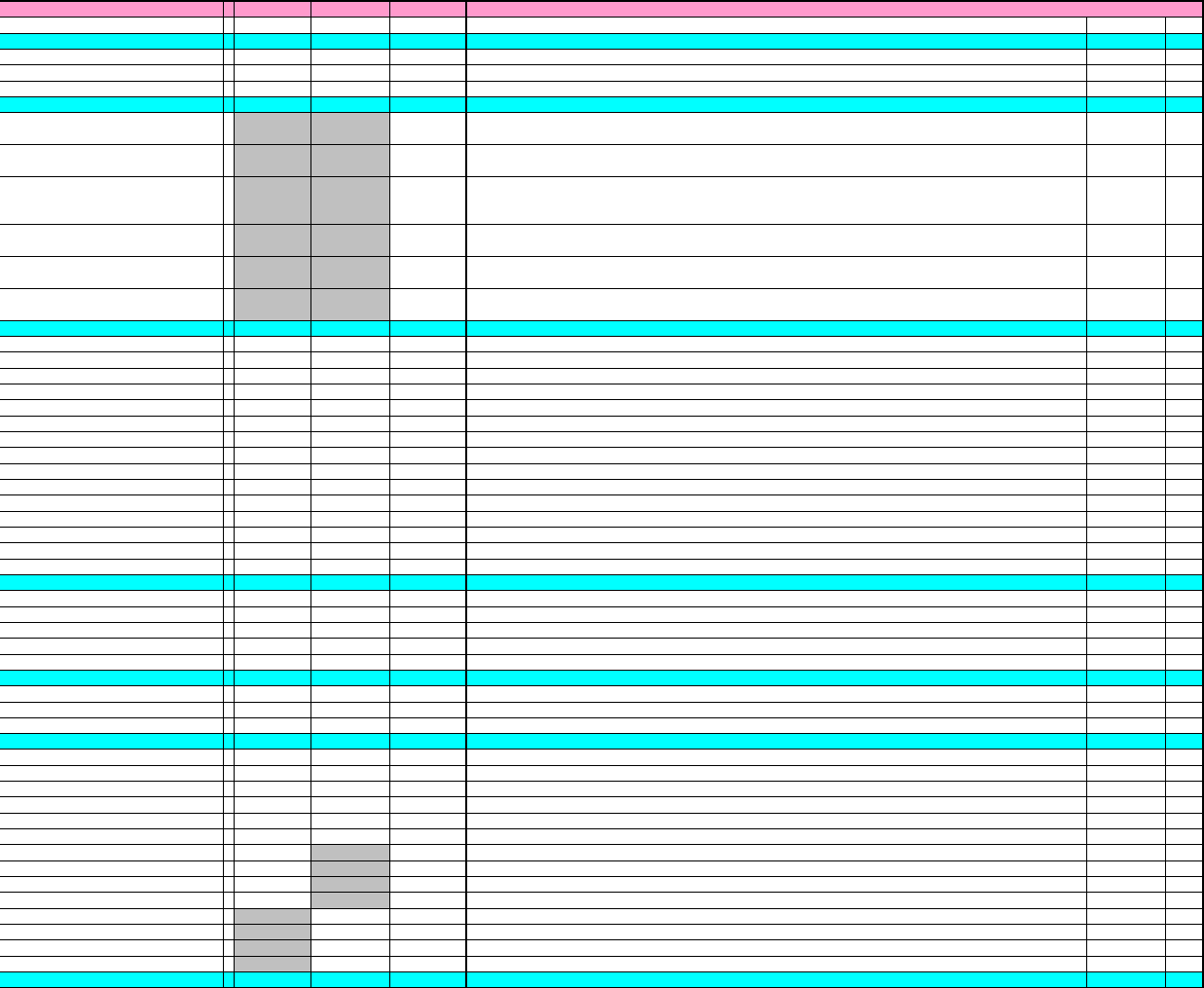
XP Proper Data ListType-II vol.3
Issue Date:2003/6/17
Item XP142
X
P242 Input Rang
e
Explanation
Editing
Reboot
__WaitNextMcOnDelayTimer = 00
0~300 Sets the delay timer (sec) for waiting for signal from next machine.
User Can Edit
________CYCLE_STEAL_______
_
__CycleStealStartTim
e
= 55
More than 0 Set the amount of time (min) before a cycle steal is carried out.
User Can Edit
__CycleStealTerm = 10 10
More than 0 Set the difference (µm) for the fiducial mark measured when a cycle steal is carried out.
User Can Edit
__CycleStealDistanceLimi
t
= 100 100
More than 0
A
n error occurs if the camera distance (µm) obtained during cycle steal exceeds this value.
User Can Edit
_________AUTO_SETUP_______
_
=
__ASSMCNum = 00
0~3
S
e
t
s
th
e au
t
oma
ti
c c
h
angeover
fl
ag.
E
n
t
er
th
e num
b
er o
f
mac
hi
nes
(1
~
3)
i
n
th
e group c
h
angeover.
Th
e
machine must be restarted to register this setting.
User Can Edit
○
__MCComPort = 10000 10000
10000
~
999
99
S
e
t
s
th
e au
t
oma
ti
c c
h
angeover
fl
ag.
C
onnec
ti
on por
t
num
b
ers
f
or
fi
rs
t
mac
hi
ne an
d
o
th
er mac
hi
nes
i
n
th
e
group (10000 to 99999). The machine must be started to register this setting.
User Can Edit
○
__PCComPort = 10000 10000
10000~999
99
S
e
t
s
th
e au
t
oma
ti
c c
h
angeover
fl
ag.
C
onnec
ti
on por
t
num
b
ers
f
or
fi
rs
t
mac
hi
ne
i
n
th
e group, an
d
IJ
process. (10000 to 99999). This setting is only required for the first machine. The machine must be
restarted to register this setting.
User Can Edit
○
__ASSFeederChk = 00
0~2
S
pec
ifi
es
th
e au
t
oma
ti
c c
h
angeover
fl
ag.
F
ee
d
er se
t
up con
fi
rma
ti
on me
th
o
d
se
tti
ng.
0
:
N
o
t
use
d
,
1:Check changed slots only. 2:Check all slots.
User Can Edit
○
__ASSFeederChkAllSet = 00
0~1
S
pec
ifi
es
th
e au
t
oma
ti
c c
h
angeover
fl
ag.
D
e
t
erm
i
nes w
h
e
th
er or no
t
th
e
"b
a
t
c
h
OK"
b
u
tt
on
di
sp
l
ays a
t
th
e
feeder setup check. The machine must be restarted to register this setting. 0: Do not display, 1: Display.
User Can Edit
○
__ASSetupInfoDisp = 00
0~1
A
u
t
oma
ti
c c
h
angeover
fl
ag se
tti
ng.
D
e
t
erm
i
nes w
h
e
th
er or no
t
th
e au
t
oma
ti
c c
h
angeover
"S
e
t
up
Information" dialog box displays.
User Can Edit
○
_________DEBUG_FLAG_______
_
=
__DebugFlag1 = 00
None
User Cannot Edit
__DebugFlag
2
= 00
None
User Cannot Edit
__DebugFlag
3
= 00
None
User Cannot Edit
__DebugFlag
4
= 00
None
User Cannot Edit
__DebugFlag
5
= 00
None
User Cannot Edit
__DebugFlag
6
= 00
None
User Cannot Edit
__DebugFlag
7
= 00
None
User Cannot Edit
__DebugFlag
8
= 00
None
User Cannot Edit
__DebugFlag
9
= 00
None
User Cannot Edit
__DebugFlag1
0
= 00
None
User Cannot Edit
__DebugBP = 00
0~3
User Cannot Edit
__DebugDL
L
= 00
0~3
User Cannot Edit
__DebugBML = 00
0~3
User Cannot Edit
__DebugPartsChec
k
= 00
0~3
User Cannot Edit
__CStructChec
k
= 00
0~1
User Cannot Edit
○
_____CONV_DELAY_TIMER_____
_
=
__InArrvOnDelayTime
r
= 10 10
More than 0 Set the delay timer for the in-conveyor arrival sensor to come on (msec).
User Can Edit
__MainDecOnDelayTime
r
= 10 10
More than 0 Set the delay timer for the main conveyor deceleration sensor to come on (msec).
User Can Edit
__MainArrvOnDelayTimer = 10 10
More than 0 Set the delay timer for the main conveyor arrival sensor to come on (msec).
User Can Edit
__MainPassOnDelayTime
r
= 10 10
More than 0 Set the delay timer for the main conveyor pass through sensor to come on (msec).
User Can Edit
__OutPassOnDelayTime
r
= 10 10
More than 0 Set the delay timer for the out-conveyor pass through sensor to come on (msec).
User Can Edit
_________TOUCH_PANEL______
_
=
__TouchPanelTyp
e
= 11
0~2 Touch panel usage setting. 0:Touch panel is not used. 1:EMT0550 AHL-71 is used, 2:IMES7512 is used.
User Cannot Edit
__TPDblClickSpee
d
= 350 350
100~3000 Sets the mouse double-click and identification time (msec).
User Cannot Edit
__TPDblClickDistanc
e
= 30 30
1~120 Sets the distance between clicks which is recognized as a double-click.
User Cannot Edit
_________SERVO_LIMIT______
_
=
X_PlusLimi
t
= 835 835
None Sets the permissable servo X-axis plus-direction travel range (mm).
Calibration Data
○
X_MinusLimit = 00
None Sets the permissable servo X-axis minus-direction travel range (mm).
Calibration Data
○
Y_PlusLimi
t
= 813 1174
None Sets the permissable servo Y-axis plus-direction travel range (mm).
Calibration Data
○
Y_MinusLimit = 00
None Sets the permissable servo Y-axis minus-direction travel range (mm).
Calibration Data
○
Z_PlusLimi
t
= 14.5 55
None Sets the permissable servo Z-axis plus-direction travel range (mm).
Calibration Data
○
Z_MinusLimit = 00
None Sets the permissable servo Z-axis minus-direction travel range (mm).
Calibration Data
○
F_PlusLimi
t
= 4.5 0
None Sets the permissable servo F-axis plus-direction travel range (mm).
Calibration Data
○
F_MinusLimit = -10.8 0
None Sets the permissable servo F-axis minus-direction travel range (mm).
Calibration Data
○
G_PlusLimit = 4.5 0
None Sets the permissable servo G-axis plus-direction travel range (mm).
Calibration Data
○
G_MinusLimit = -10.8 0
None Sets the permissable servo G-axis minus-direction travel range (mm).
Calibration Data
○
T_PlusLimit = 0 520
None Sets the permissable servo T-axis plus-direction travel range (mm).
Calibration Data
○
T_MinusLimit = 00
None Sets the permissable servo T-axis minus-direction travel range (mm).
Calibration Data
○
U_PlusLimi
t
= 0 532
None Sets the permissable servo U-axis plus-direction travel range (mm).
Calibration Data
○
U_MinusLimit = 00
None Sets the permissable servo U-axis minus-direction travel range (mm).
Calibration Data
○
_______JOG_BASE_SPEED_____
_
=
4/12
XP Type-Ⅱ Proper Data List vol.3

XP Proper Data ListType-II vol.3
Issue Date:2003/6/17
Item XP142
X
P242 Input Rang
e
Explanation
Editing
Reboot
X_jogBaseSpeed = 10000 10000
More than 0 Minimum X-axis inching speed setting
User Cannot Edit
Y_jogBaseSpeed = 10000 10000
More than 0 Minimum Y-axis inching speed setting
User Cannot Edit
Z_jogBaseSpeed = 2000 10000
More than 0 Minimum Z-axis inching speed setting
User Cannot Edit
Q_jogBaseSpeed = 50000 50000
More than 0 Minimum Q-axis inching speed setting
User Cannot Edit
R_jogBaseSpeed = 50000 50000
More than 0 Minimum R-axis inching speed setting
User Cannot Edit
F_jogBaseSpeed = 10000 10000
More than 0 Minimum F-axis inching speed setting
User Cannot Edit
G_jogBaseSpeed = 10000 10000
More than 0 Minimum G-axis inching speed setting
User Cannot Edit
T_jogBaseSpeed = 10000 10000
More than 0 Minimum T-axis inching speed setting
User Cannot Edit
U_jogBaseSpeed = 10000 10000
More than 0 Minimum U-axis inching speed setting
User Cannot Edit
______SERVO_PARAMETER_____
_
=
x_MaxV = 16000000 16000000
More than 0 Sets the maximum X-axis speed.
User Cannot Edit
x_Max
A
= 240000000 230000000
More than 0 Sets the maximum X-axis acceleration.
User Cannot Edit
x_ptpGain = 80 100
More than 0 Sets the gain during X-axis travel.
User Cannot Edit
x_stGain = 80 100
More than 0 Sets the gain during X-axis positioning.
User Cannot Edit
x_afterGain = 60 50
More than 0 Sets the gain during X-axis stop.
User Cannot Edit
x_P_CON_Star
t
= 66
More than 0 Sets the X-axis P_CON start time (msec).
User Cannot Edit
x_integralGain = 60 50
More than 0 Sets the X-axis integral gain.
User Cannot Edit
x_AxisValid = 11
More than 0 X-axis enabled/disabled setting. 0:X-axis disabled (ignore), 1: X-axis enabled.
User Cannot Edit
x_spare2 = 11
More than 0 X-axis enabled/disabled setting. 0:X-axis disabled (ignore), 1: X-axis enabled.
User Cannot Edit
x_CurveNo = 11
More than 0 Specifies the X-axis cam curve number. 1: Distorted sine, 2:Cycloid curve, 3:NC2, etc.
User Cannot Edit
y_Max
V
= 25000000 25000000
More than 0 Sets the maximum Y-axis speed.
User Cannot Edit
y_Max
A
= 372000000 448000000
More than 0 Sets the maximum Y-axis acceleration.
User Cannot Edit
y_ptpGain = 鉄プーリー:130 130
More than 0 Sets the gain during Y-axis travel.
User Cannot Edit
y_stGain = 鉄プーリー:130 130
More than 0 Sets the gain during Y-axis positioning.
User Cannot Edit
y_afterGain = 80 120
More than 0 Sets the gain during Y-axis stop.
User Cannot Edit
y_P_CON_Star
t
= 66
More than 0 Sets the Y-axis P_CON start time (msec).
User Cannot Edit
y_integralGain = 30 120
More than 0 Sets the Y-axis integral gain.
User Cannot Edit
y_AxisValid = 11
More than 0 Y-axis enabled/disabled setting. 0:Y-axis disabled (ignore), 1: Y-axis enabled.
User Cannot Edit
y_spare2 = 11
More than 0 Y-axis enabled/disabled setting. 0:Y-axis disabled (ignore), 1: Y-axis enabled.
User Cannot Edit
y_CurveNo = 11
More than 0 Specifies the Y-axis cam curve number. 1: Distorted sine, 2:Cycloid curve, 3:NC2, etc.
User Cannot Edit
z_Max
V
= 15000000 15000000
More than 0 Sets the maximum Z-axis speed.
User Cannot Edit
z_Max
A
= 1600000000 830000000
More than 0 Sets the maximum Z-axis acceleration.
User Cannot Edit
z
_p
t
p
Gain
= 200 180
More than 0 Sets the gain during Z-axis travel.
User Cannot Edit
z
_
stGain
= 200 180
More than 0 Sets the gain during Z-axis positioning.
User Cannot Edit
z_afterGain = 200 180
More than 0 Sets the gain during Z-axis stop.
User Cannot Edit
z_P_CON_Star
t
= 66
More than 0 Sets the Z-axis P_CON start time (msec).
User Cannot Edit
z_integralGain = 150 180
More than 0 Sets the Z-axis integral gain.
User Cannot Edit
z_AxisValid = 11
More than 0 Z-axis enabled/disabled setting. 0:Z-axis disabled (ignore), 1: Z-axis enabled.
User Cannot Edit
z_spare2 = 11
More than 0 Z-axis enabled/disabled setting. 0:Z-axis disabled (ignore), 1: Z-axis enabled.
User Cannot Edit
z_CurveNo = 31
More than 0 Specifies the Z-axis cam curve number. 1: Distorted sine, 2:Cycloid curve, 3:NC2, etc.
User Cannot Edit
q_MaxV = 315000000 210000000
More than 0 Sets the maximum Q-axis speed.
User Cannot Edit
q_Max
A
= 13000000000 1000000000
0
More than 0 Sets the maximum Q-axis acceleration.
User Cannot Edit
q_ptpGain = 118 225
More than 0 Sets the gain during Q-axis travel.
User Cannot Edit
q_stGain = 118 225
More than 0 Sets the gain during Q-axis positioning.
User Cannot Edit
q_afterGain = 100 300
More than 0 Sets the gain during Q-axis stop.
User Cannot Edit
q_P_CON_Star
t
= 63
More than 0 Sets the Q-axis P_CON start time (msec).
User Cannot Edit
q_integralGain = 100 300
More than 0 Sets the Q-axis integral gain.
User Cannot Edit
q_AxisValid = 11
More than 0 Q-axis enabled/disabled setting. 0:Q-axis disabled (ignore), 1: Q-axis enabled.
User Cannot Edit
q_spare2 = 11
More than 0 Q-axis enabled/disabled setting. 0:Q-axis disabled (ignore), 1: Q-axis enabled.
User Cannot Edit
q_CurveNo = 31
More than 0 Specifies the Q-axis cam curve number. 1: Distorted sine, 2:Cycloid curve, 3:NC2, etc.
User Cannot Edit
r_MaxV = 160000000 0
More than 0 Sets the maximum R-axis speed.
User Cannot Edit
r_Max
A
= 12000000000 0
More than 0 Sets the maximum R-axis acceleration.
User Cannot Edit
r_ptpGain = 100 0
More than 0 Sets the gain during R-axis travel.
User Cannot Edit
r_stGain = 100 0
More than 0 Sets the gain during R-axis positioning.
User Cannot Edit
r_afterGain = 100 0
More than 0 Sets the gain during R-axis stop.
User Cannot Edit
r_P_CON_Start = 60
More than 0 Sets the R-axis P_CON start time (msec).
User Cannot Edit
r_integralGain = 60 0
More than 0 Sets the R-axis integral gain.
User Cannot Edit
r_AxisValid = 10
More than 0 R-axis enabled/disabled setting. 0:R-axis disabled (ignore), 1: R-axis enabled.
User Cannot Edit
r_spare2 = 10
More than 0 R-axis enabled/disabled setting. 0:R-axis disabled (ignore), 1: R-axis enabled.
User Cannot Edit
r
_
CurveNo
= 30
More than 0 Specifies the R-axis cam curve number. 1: Distorted sine, 2:Cycloid curve, 3:NC2, etc.
User Cannot Edit
f_MaxV = 8500000 0
More than 0 Sets the maximum F-axis speed.
User Cannot Edit
5/12
XP Type-Ⅱ Proper Data List vol.3