XP Type II 工程师培训手册 (2.0).pdf.pdf - 第13页
FK-9F98-34 XP T ype II Series T raining T ext for Service Engineers Edition 2.0 XP142E – Chapter 1 Initial Adjustment Page 3 of 8 Fuji Machine Mfg. Co., Ltd.Okazaki 1.3 Lubrication 1. Apply lubricant to the following are…
FK-9F98-34 XP Type II Series Training Text for Service Engineers
Edition 2.0 XP142E – Chapter 1 Initial Adjustment Page 2 of 8
Fuji Machine Mfg. Co., Ltd.Okazaki
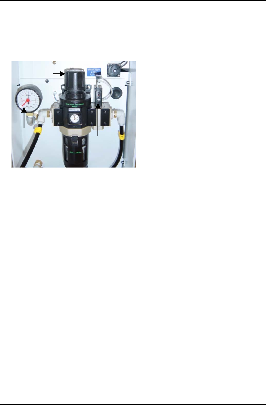
Air Hose Connection
1. Connect the hose to the air inlet at the machine.
2. Pull up on the regulator knob to release the lock.
Pressure
Gage
Vacuum
Sensor
Regulator Knob
3. Turn the regulator knob until the pressure level indicated at the regulator shows 0.5Mpa
(5kgf/cm2).
4. Push down the regulator knob to lock it.
5. Adjust the screw on the top of the vacuum sensor so that the 200-volt power supply to the
servos cuts out when the air pressure drops to 0.4Mpa and below.
6. Select [Maintenance A] – [I/O Check] – [Y016 VacuumPump] – [ON] and confirm that the
pressure gage shows negative pressure.
7. If the dial indicates positive pressure the power cable connection may be reverse phased.
8. In this case turn the machine power OFF, trip the breaker and disconnect the power cable
from the mains socket.
9. Check that the power supply connection is correct, and then confirm the power cable itself
is not reverse phased.
SMT Equipment Quality Assurance Dept.
1 – 2 CS Section

FK-9F98-34 XP Type II Series Training Text for Service Engineers
Edition 2.0 XP142E – Chapter 1 Initial Adjustment Page 3 of 8
Fuji Machine Mfg. Co., Ltd.Okazaki
1.3 Lubrication
1. Apply lubricant to the following areas:
Lubrication points Lubrication Type
Y-axis ball screw Daphne Eponex No.2
Z-axis ball screw Daphne Eponex No.2
Spline Shaft Daphne Eponex No.2
Theta and R axes gears Daphne Eponex No.2
Conveyor ball screw Daphne Eponex No.2
Conveyor LM rail Daphne Eponex No.2
Sliding parts of lifter plate link arm Daphne Eponex No.2
Sliding parts of cutter link arm Daphne Eponex No.2
Cutter LM rail Daphne Eponex No.2
F and G axes cams Daphne Eponex No.2
Nozzle Pistons AFC Grease
Spool Axes AFC Grease
Conveyor Chain Biral T and D
Note: Apply anticorrosion spray to the machine base, brackets, and other metal surfaces, to prevent
rust.
Note: Do not over apply lubricant to the ball screws, helical gears, LM guide rails, or other parts of the
machine that rotate or move at high velocity. Over lubrication may result in the lubricant being flung
around the machine and interfering with the sensors, vision processing, and other aspects of the
machine operation.
SMT Equipment Quality Assurance Dept.
1 – 3 CS Section
FK-9F98-34 XP Type II Series Training Text for Service Engineers
Edition 2.0 XP142E – Chapter 1 Initial Adjustment Page 4 of 8
Fuji Machine Mfg. Co., Ltd.Okazaki
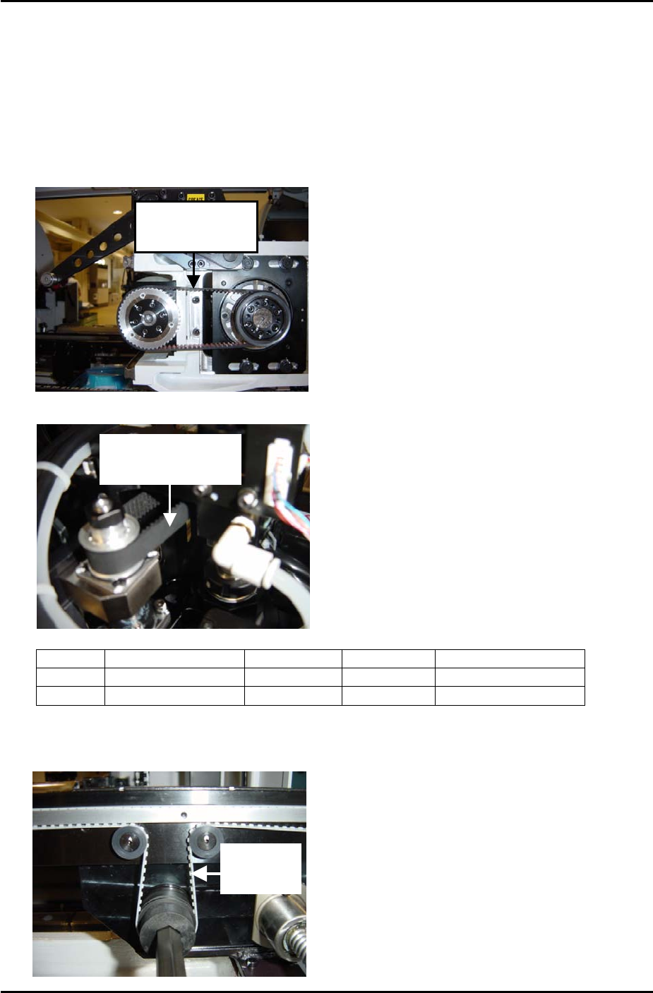
1.4 Belt Tension Measurement
1. Equipment: belt tension meter.
2. Press the emergency stop button to cut the 200-volt power supply to the servos and then
bring the Y and Z axes to the minus mechanical stoppers.
3. Refer to the following illustrations and check that the tension of each belt is within the
appropriate range:
Measure Y-axis
here at side 2
Measure Z-axis
here at side 1
Belt unit weight Belt width Belt span Frequency range
Y axis
0.4 gf/mm 15mm 130mm 145 –163 Hz
Z axis
0.2 gf/mm 8mm 110mm 206 – 228Hz
4. Finally check the tension of the fixed rail and adjustable rail conveyor belts, measure at the
point indicated in the photo below. Tension should be in the range 425 ~ 445 Hz.
Measure
Here
SMT Equipment Quality Assurance Dept.
1 – 4 CS Section