XP Type II 工程师培训手册 (2.0).pdf.pdf - 第146页
FK-9F98-34 XP T ype II Series T raining T ext for Service Engineers Edition 2.0 XP242E – Chapter 5 Peripheral Adjustm ents Page 8 of 16 5.3 MFU Cylinder Sensors Adjustment 1. Note that there are two sensors on each clamp…
FK-9F98-34 XP Type II Series Training Text for Service Engineers
Edition 2.0 XP242E – Chapter 5 Peripheral Adjustments Page 7 of 16
Make sure that it is not possible to turn
the fiber sensor attachment b
y
hand
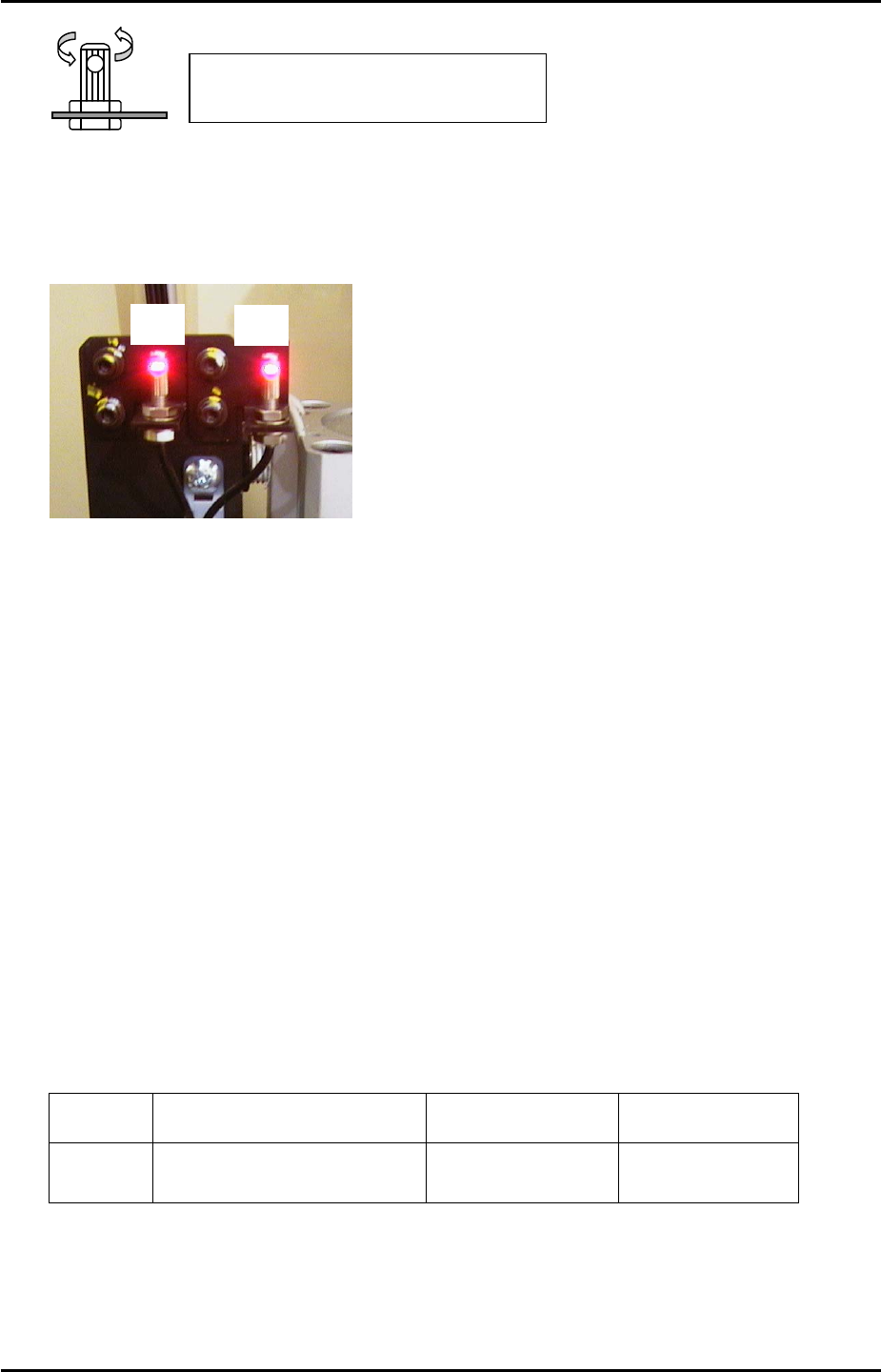
12. Now remove the wire jig and fine adjust the position of the sensors to find the position
where the number on the digital display is maximised. This maximum value should be
greater than 3. If the value is 3 or less check the fiber wiring and clean the sensor lens.
Side 1
F2
F1
13. After the sensors have been set at the optimum position remove the jigs and turn the dial
switch on the sensor amplifier until “2P” flashes in the digital display.
14. Press the dial once so that the “2” in “2P” flashes.
15. Block the sensor by hand and press the dial switch once. A number 1~100 will display on
the digital display, this must be greater than 10.
16. Press the dial switch once so that SET flashes in the mode display.
17. Turn the dial switch so that RUN flashes in the mode display.
18. Press the dial switch once to complete the adjustment.
19. Finally select [Maintenance A] – [I/O Check] and check the sensor operation by I/O.
There is only one I/O channel:
Sensor I/O Output when not
interrupted
Output when
interrupted
F1/F2 X026 Side1 TpsetDetect ON (with buzzer) OFF
Fuji Machine Mfg. Co., Ltd. Okazaki.
SMT Equipment Quality Assurance Dept.
5 – 7 CS Section
FK-9F98-34 XP Type II Series Training Text for Service Engineers
Edition 2.0 XP242E – Chapter 5 Peripheral Adjustments Page 8 of 16
5.3 MFU Cylinder Sensors Adjustment
1. Note that there are two sensors on each clamping cylinder.
2. The clamp check sensors (X02E side1MfuUpChk) should be adjusted so that they are ON
0.3mm from the clamp upper limit, and OFF 0.8mm from the clamp upper limit. In order
to adjust them, please follow the procedure below:
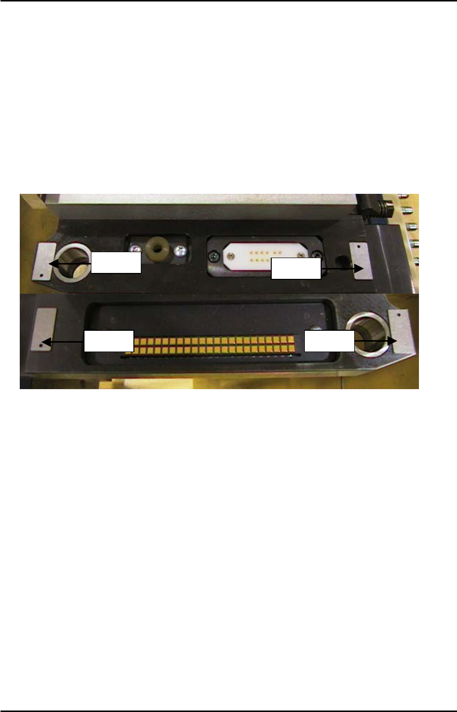
3. Place 0.3mm spacers in the four corners of the MFU clamping surface as illustrated
below:
Spacer
Spacer
Spacer Spacer
4. Clamp the MFU.
5. Slide the clamp check sensors DOWN until they go OFF then slide them back UP until
they just come ON then tighten the screw (X02E side1MfuUpChk).
6. Unclamp the MFU and replace the 0.3mm spacers with 0.8mm spacers.
7. Clamp the MFU and confirm that the clamp check sensors (X02E side1MfuUpChk) are
OFF.
8. Unclamp the MFU and slide the unclamp check sensors UP until they go OFF and then
slide them back DOWN until they come ON. From the position they first come ON slide
them a further 1mm DOWN and tighten the screw. (X02F side1MfuDownChk).
9. Repeat the procedure for side 2 (X03E side2MfuUpChk) and (X03F side2MfuDownChk).
Fuji Machine Mfg. Co., Ltd. Okazaki.
SMT Equipment Quality Assurance Dept.
5 – 8 CS Section
FK-9F98-34 XP Type II Series Training Text for Service Engineers
Edition 2.0 XP242E – Chapter 5 Peripheral Adjustments Page 9 of 16
5.4 Waste Tape Cutter
Warning: The Waste tape cutter plate is an extremely heavy item. Please handle with
care. Also, take extreme care when handling (or working in the vicinity of) the cutter blade.
It may cause damage or personal injury.
1. Remove the MFU, and the waste tape cutter cover.
2. For the waste tape cutter cylinder air valve speed controller adjustments please refer to
the following table:
Speed Controller Air Tube Line Number of turns from fully closed
Cutter close valve U5 7.5
Cutter open valve U6 8
Cutter Engagement Adjustment
1. Ensure the gap between the movable cutter and the fixed cutter is within 0 ~ 0.03 mm,
when both cutters are engaged.
2. Ensure there are no nicks or cracks in the cutter blade.
Stopper Position adjustment
1. Position the stopper just at the end of the cylinder stroke.
2. Lock the stopper 1.5 ~ 2.0mm in from this position.
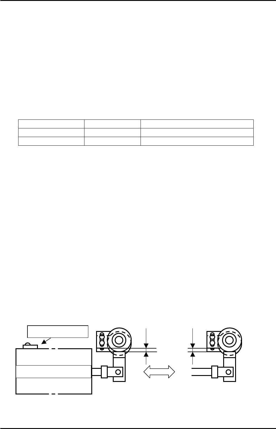
Retract Limit Sensor Adjustment
1. With the stopper positioned, adjust the sensor so that when the cutter is moved to its
retract limit the I/O X031 Side1TpCutOrgPos comes on 1.5 mm in from the cylinder
stoke end.
Retract limit senso
r
1.5~2.0mm
Retract limit (Cutter Open)
Forward limit
(
Cutter close
)
Cutter c
y
linder
Fuji Machine Mfg. Co., Ltd. Okazaki.
SMT Equipment Quality Assurance Dept.
5 – 9 CS Section