XP Type II 工程师培训手册 (2.0).pdf.pdf - 第140页
FK-9F98-34 XP T ype II Series T raining T ext for Service Engineers Edition 2.0 XP242E – Chapter 5 Peripheral Adjustm ents Page 2 of 16 4. Use a dial gage to measure the device surface A and B. Please refer to the diagra…
FK-9F98-34 XP Type II Series Training Text for Service Engineers
Edition 2.0 XP242E – Chapter 5 Peripheral Adjustments Page 1 of 16
Chapter 5 Peripheral Adjustments
5.1 Adjusting the MFU
Measuring equipment: Lever type dial gauge (0.01mm).
Feeder Flatness and Parallelism Measurements
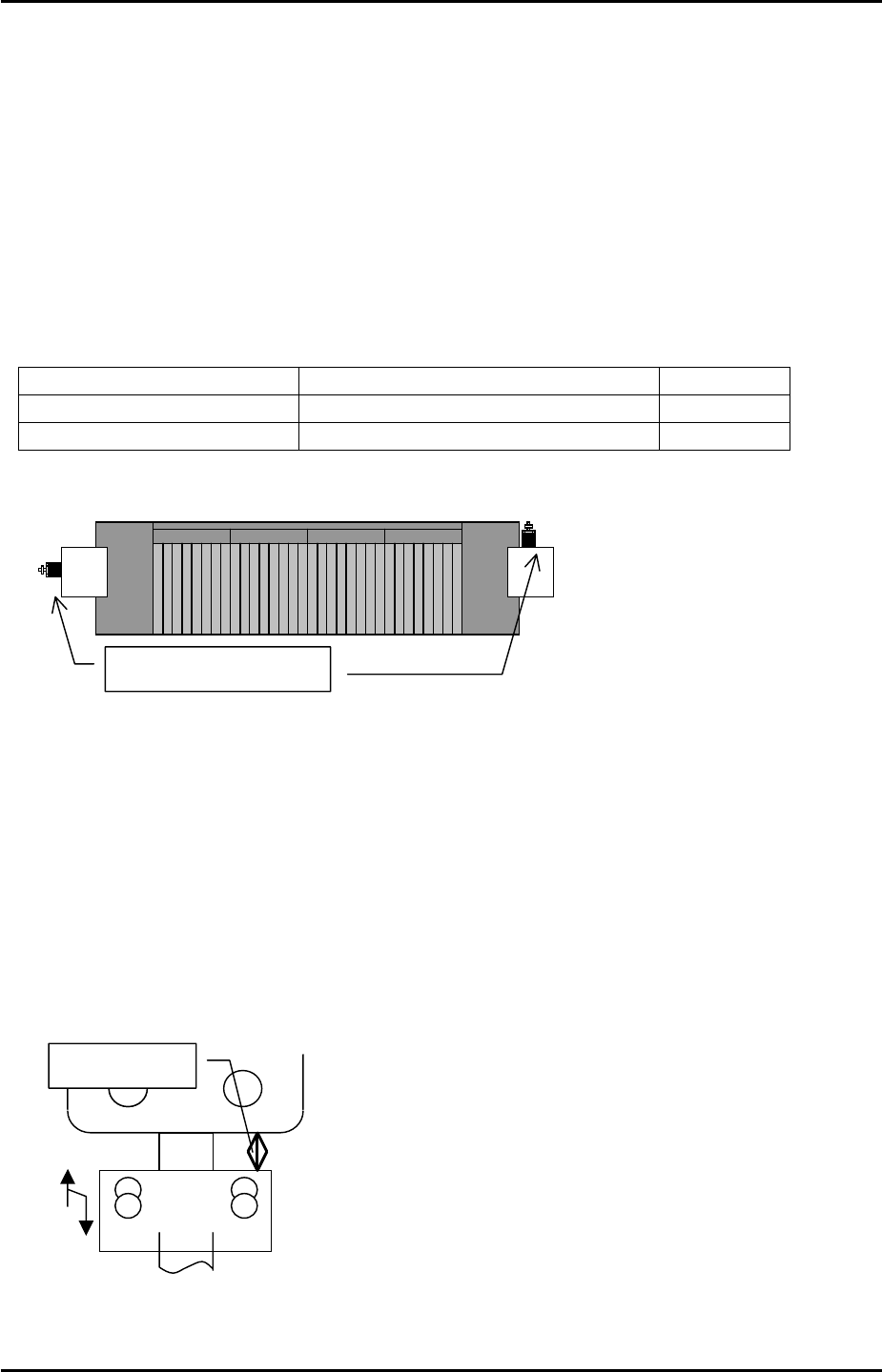
1. Adjust the MFU air valve speed controllers as follows:
Speed controller location Number of turns from fully closed Function
Upper speed controllers 2 turns from fully closed Unclamp
Lower speed controllers 3.5 turns from fully closed Clamp
D0 MFU D40
MFU Air valves
Note: ensure that there is no jolting when clamping and unclamping the MFU.
2. Clamp the MFU to the machine.
Warning: the MFU device table is very heavy. Please take extreme care to prevent your
finger/hand getting caught when carrying out height or other adjustments on the MFU.
3. Adjust the MFU adjustment stopper, so that when the MFU is clamped, the gap between
the stopper and the MFU device table underside is approximately 20mm. Please see the
diagram below:
A
pprox. 20mm
Fuji Machine Mfg. Co., Ltd. Okazaki.
SMT Equipment Quality Assurance Dept.
5 – 1 CS Section
FK-9F98-34 XP Type II Series Training Text for Service Engineers
Edition 2.0 XP242E – Chapter 5 Peripheral Adjustments Page 2 of 16
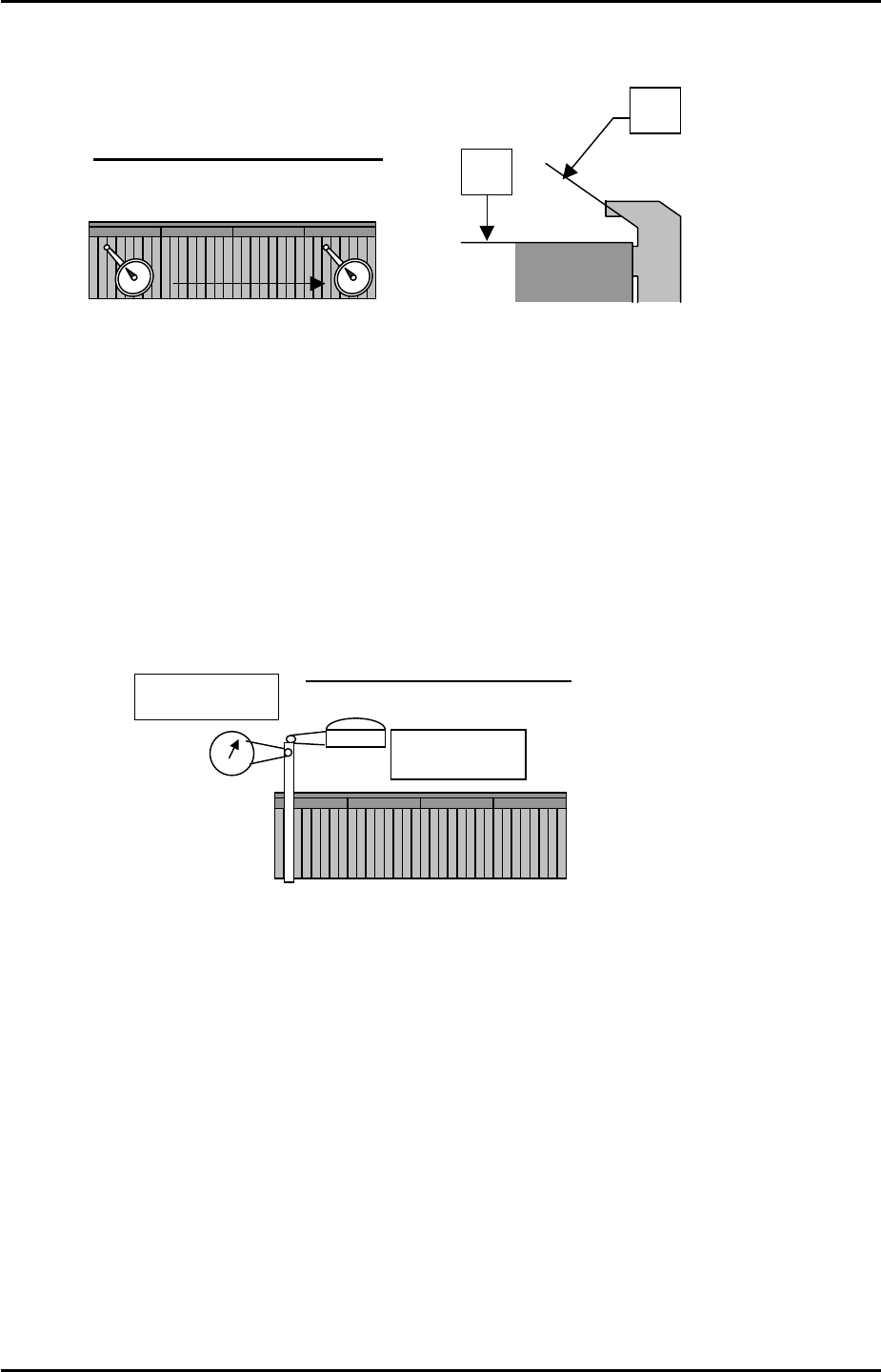
4. Use a dial gage to measure the device surface A and B. Please refer to the diagram
below:
A
Tolerance: 0.05 mm / 800mm
D40
D1
0
B
5. Measure any additional MFUs in the same manner.
6. After measuring all of the MFUs, check the static accuracy of the MFUs at the clamping
position.
7. Choose one device as the reference MFU, and clamp the MFU to side 1.
8. Mount the device jig in slot No.2. Use an extension bar to attach the dial gage to the
placement head. Put the tip of the dial gage to the device jig in the Z and Y directions.
Please refer to the illustration:
Y-direction
Z-direction
Tolerance: within 0.050mm
9. Set the dial to 0.
Jog the head in the X-direction so that the dial gage tip leaves the jig.
Record the present Y-axis servo count, and then unclamp the MFU.
10. Clamp the other MFU.
11. After clamping the MFU, mount the device jig in slot No.2 and turn the servo ON. Jog the
X-axis and check the difference between the position of the two MFUs in the Y and Z
directions.
12. Repeat the procedure for any other MFUs.
Fuji Machine Mfg. Co., Ltd. Okazaki.
SMT Equipment Quality Assurance Dept.
5 – 2 CS Section
FK-9F98-34 XP Type II Series Training Text for Service Engineers
Edition 2.0 XP242E – Chapter 5 Peripheral Adjustments Page 3 of 16
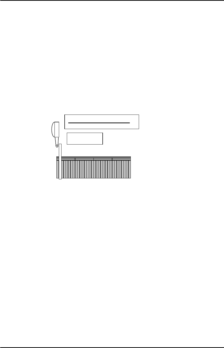
X Direction Static Accuracy Check
1. Clamp the reference MFU used in previous steps to side 1.
2. Mount the device jig to device No.2 and set the dial gauge tip to the X-direction.
3. Set the dial to 0. Jog in the Y-direction to detach the dial gage tip from the jig. Record the
present X-axis servo counter. Unclamp the MFU.
4. Clamp another MFU, then mount the device jig to device No.2 and turn the servo ON. Jog
the X axis and check the difference in the X-direction.
X-direction
Tolerance: within 0.050mm
5. Repeat the procedure for any other MFUs
Device I/O Port Check
1. Load the device I/O check feeder on the device table, and use direct I/O (Y040
PartsSendD1) and (Y07F PartsSendD40) to check that all the device position I/0s are
operational.
Note: Use a cloth to wipe any dirt from the MFU connectors.
Fuji Machine Mfg. Co., Ltd. Okazaki.
SMT Equipment Quality Assurance Dept.
5 – 3 CS Section