XP Type II 工程师培训手册 (2.0).pdf.pdf - 第151页
FK-9F98-34 XP T ype II Series T raining T ext for Service Engineers Edition 2.0 XP242E – Chapter 5 Peripheral Adjustm ents Page 13 of 16 3. Use the arrow keys to set the display to “Sor”. 4. Press [SET] once and then use…
FK-9F98-34 XP Type II Series Training Text for Service Engineers
Edition 2.0 XP242E – Chapter 5 Peripheral Adjustments Page 12 of 16
4. Turn I/O Y021 NozzleUnhold OFF when the nozzle jig is attached. The nozzle vacuum
sensor should show a value of –70Mpa or more negative.
5. Turn I/O Y020 PartsPickUp ON. The parts vacuum sensor should show –70Mpa or more
negative, when a part is vacuumed.
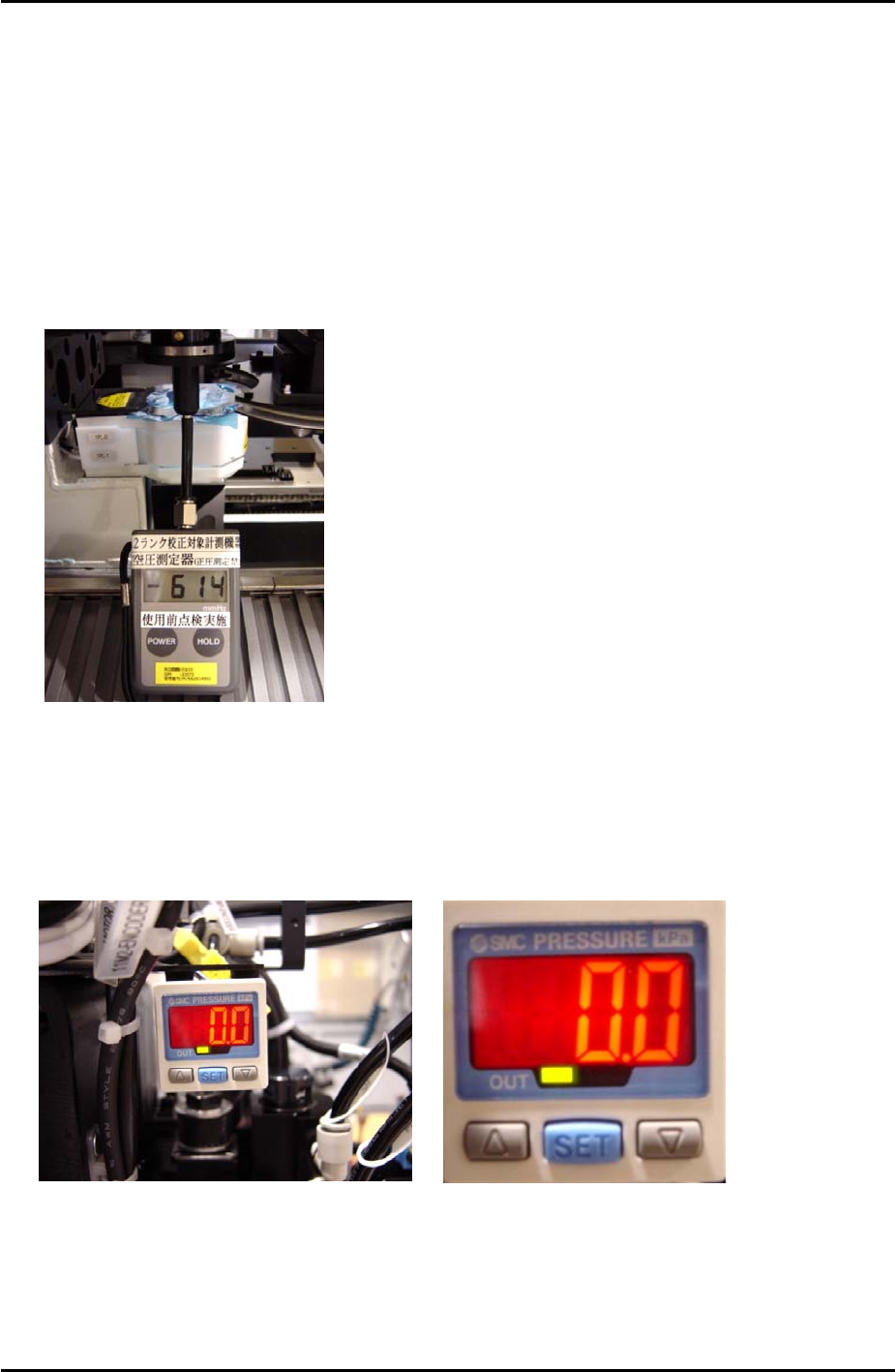
6. Attach the manometer to the nozzle jig. Turn Y021 NozzleUnhold OFF, and attach the
nozzle jig to the placing head. Turn I/O Y020 PartsPickUp ON. Under these conditions
the manometer should indicate the vaccuum pressure is –600mmHg (-79.99kPa) or more
negative.
7. Adjust the parts air blow speed controller. Turn Y01D PartsPickUpDes ON, and Y020
PartsPickUp OFF, then adjust the speed controller until the manometer indicates the air
blow pressure is +75 mmHg (9.99kPa).
SMC Pressure Sensor Setting
1. To unlock the pressure sensor, press and hold the [SET] button for more than 6 seconds.
Use the arrow keys to select unlock and then press [SET] to return to the original screen.
2. Press the [SET] button for more than 2 seconds.
Fuji Machine Mfg. Co., Ltd. Okazaki.
SMT Equipment Quality Assurance Dept.
5 – 12 CS Section

FK-9F98-34 XP Type II Series Training Text for Service Engineers
Edition 2.0 XP242E – Chapter 5 Peripheral Adjustments Page 13 of 16
3. Use the arrow keys to set the display to “Sor”.
4. Press [SET] once and then use the arrow keys to set the display to “HYS”.
5. Press [SET] once and then use the arrow keys to set the display to “nC”.
6. Press [SET] once and use the arrow keys to set the display to “2.5”.
7. Press [SET] once and use the arrow keys to set the display to “mAn”.
8. Press [SET] once to return to the original screen.
Airblow
1. Press [SET] once, “n_1 and a numerical value “**” flash alternately.
2. Use the arrow keys to set the numerical value to “1.4”.
3. Press [SET] for three seconds.
4. Press [SET] twice to return to original screen.
5. Finally to lock the pressure sensor press [SET] for more than 6 seconds. Use the arrow
keys to select Lock and then press [SET] to return to the original screen.
Fuji Machine Mfg. Co., Ltd. Okazaki.
SMT Equipment Quality Assurance Dept.
5 – 13 CS Section
FK-9F98-34 XP Type II Series Training Text for Service Engineers
Edition 2.0 XP242E – Chapter 5 Peripheral Adjustments Page 14 of 16
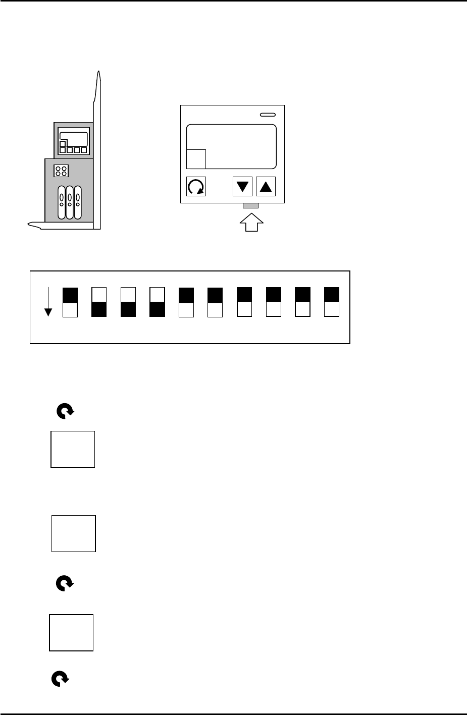
5.7 Checking the Power Remover Amplifier (Keyence AP-80A)
1. Turn the M/C power and breaker OFF.
2. Remove the front cover of the amplifier and set the jumper switches as follows:
3. Power ON.
4. Press once and the following should display:
5. Use the up and down arrow keys to set the value to –5, so the display is like this:
6. Press once and the following should display:
1 – H
“…”
1 – H
-5
ON
DPS-10-B
KEYENCE AP-80A
A
HOLD
1 – h
0
7. Press twice and the setting is finished.
Fuji Machine Mfg. Co., Ltd. Okazaki.
SMT Equipment Quality Assurance Dept.
5 – 14 CS Section