XP Type II 工程师培训手册 (2.0).pdf.pdf - 第57页
FK-9F98-34 XP T ype II Series T raining T ext for Service Engineers Edition 2.0 XP142E – Chapter 5 Peripheral Adjustm ents Page 13 of 14 Air Blow Pressure Check 1. Select [Maintenance A] – [I/O Check] – [Y01F ResetCylind…
FK-9F98-34 XP Type II Series Training Text for Service Engineers
Edition 2.0 XP142E – Chapter 5 Peripheral Adjustments Page 12 of 14
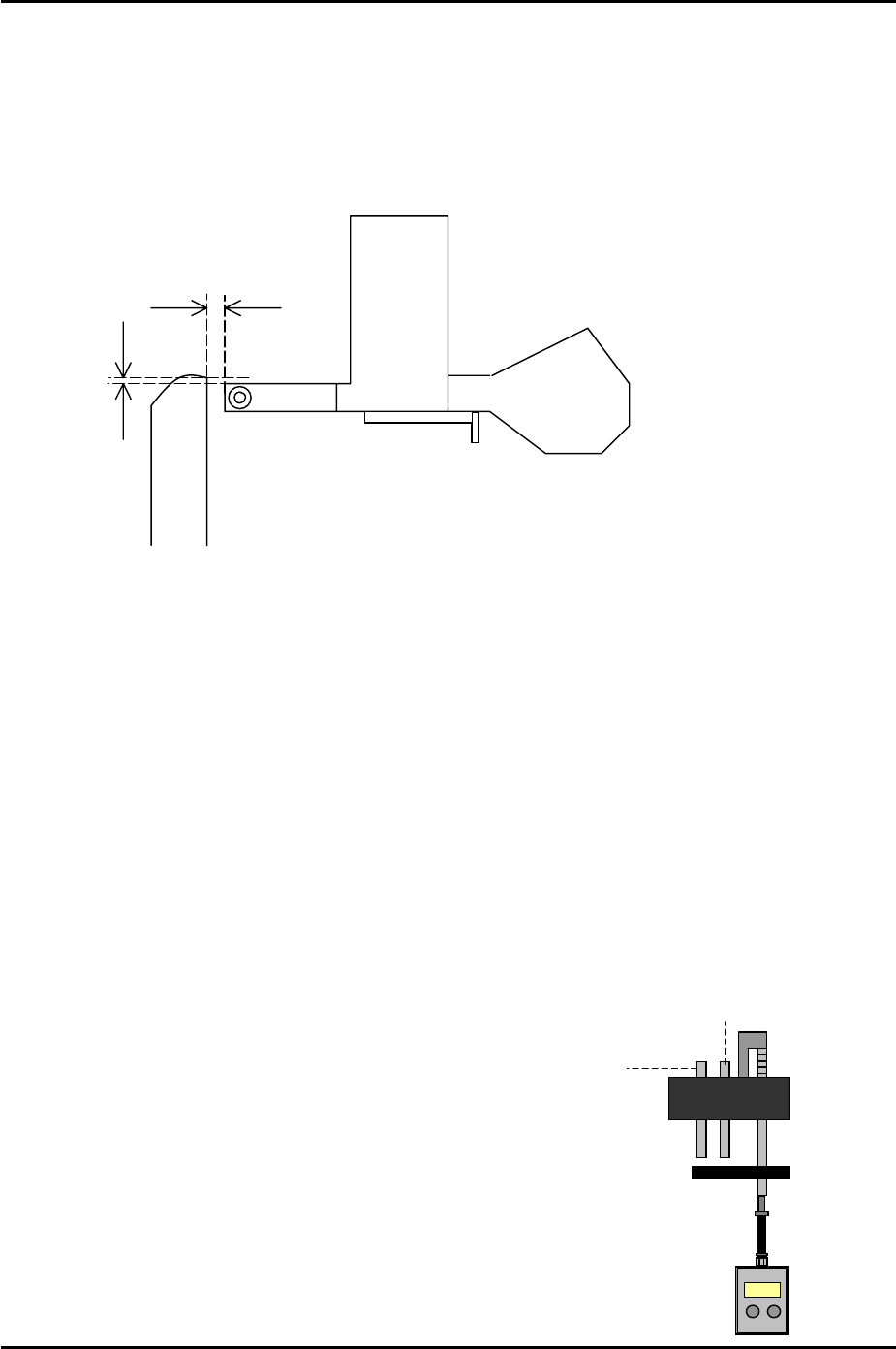
5.8 Waste Tape Duct Height Adjustment
1. Clamp the MFU and insert feeders in slots number 2 and 49.
2. Set the height of the waste tape duct approximately 1mm higher than the top of the
feeder so that there is sufficient clearance for the waste tape to feed down the duct into
the waste tape box.
Approx. 1mm
1.5 to 3.5mm
3. Set the waste tape duct 1.5 to 3.5mm from the tape feeder end in the Y-direction. Please
refer to the diagram above.
5.9 Measuring the Vacuum Pressure
1. Equipment: manometer. Nozzle and air tube.
Vacuum Pressure Check
1. Select [Maintenance A] – [I/O Check] – [Y01F ResetCylinder] – [ON] to raise the parts
vacuum pin and the air blow pin.
2. Select [Maintenance A] – [I/O check] – [Y01F ResetCylinder] – [OFF] to lower the reset
cylinder.
Air blow pin
Vacuum pin
3. Attach the nozzle and air tube at nozzle
position 1.
4. Press the nozzle No.1 vacuum pin down.
5. Select [Maintenance A] – [I/O Check] – [Y016
VacuumPump] and [Y01D PartsPickUpDes] –
[ON] and check the vacuum pressure reading
on the manometer.
6. The reading should be –600 mmHg (-79.99
kPa) or more negative.
Fuji Machine Mfg. Co., Ltd. Okazaki
SMT Equipment Quality Assurance Dept.
5 – 12 CS Section
FK-9F98-34 XP Type II Series Training Text for Service Engineers
Edition 2.0 XP142E – Chapter 5 Peripheral Adjustments Page 13 of 14
Air Blow Pressure Check
1. Select [Maintenance A] – [I/O Check] – [Y01F ResetCylinder] – [ON] to raise the parts
vacuum pin and the air blow pin.
2. Select [Maintenance A] – [I/O check] – [Y01F ResetCylinder] – [OFF] to lower the reset
cylinder.
3. Attach the nozzle, air tube and manometer at nozzle position 1.
4. Align the pusher above the nozzle number 1 piston and descend the Z-axis using the
pusher to push down the vacuum pin and the air blow pin.
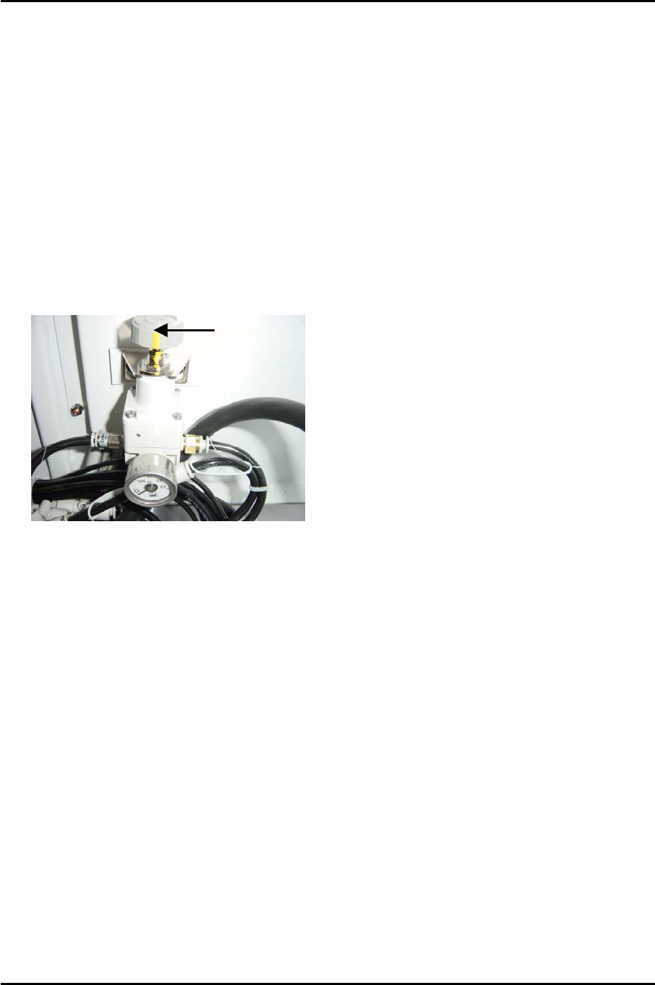
5. Select [Maintenance A] – [I/O check] – [Y016 VacuumPump] – [ON] and [Y01D
partspickUpDes] – [ON] and check the air blow pressure. Adjust the air regulator at side
2 until the pressure reading is 110 +/- 10 mmHg (14.67 +/- 1.33 kPa).
Adjust Here
6. Finally lock the air regulator.
Fuji Machine Mfg. Co., Ltd. Okazaki
SMT Equipment Quality Assurance Dept.
5 – 13 CS Section

FK-9F98-34 XP Type II Series Training Text for Service Engineers
Edition 2.0 XP142E – Chapter 5 Peripheral Adjustments Page 14 of 14
NOTES:
Fuji Machine Mfg. Co., Ltd. Okazaki
SMT Equipment Quality Assurance Dept.
5 – 14 CS Section