XP Type II 工程师培训手册 (2.0).pdf.pdf - 第25页
FK-9F98-34 XP T ype II Series T raining T ext for Service Engineers Edition 2.0 XP142E – Chapter 2 Origin settings Page 6 of 6 Fuji Machine Mfg. Co., Ltd. Okazaki 7. Also check that the minus limits for t he X, Y , and Z…
FK-9F98-34 XP Type II Series Training Text for Service Engineers
Edition 2.0 XP142E – Chapter 2 Origin settings Page 5 of 6
Fuji Machine Mfg. Co., Ltd. Okazaki
2.5 Setting the Axis Origins
1. Press the emergency stop button to cut the 200-volt power supply to the servos, then
set the X, Y and Z axes against their minus mechanical stoppers. For details of the
location of mechanical stoppers please refer to the diagrams in the “Supplementary
Information” section of this manual.
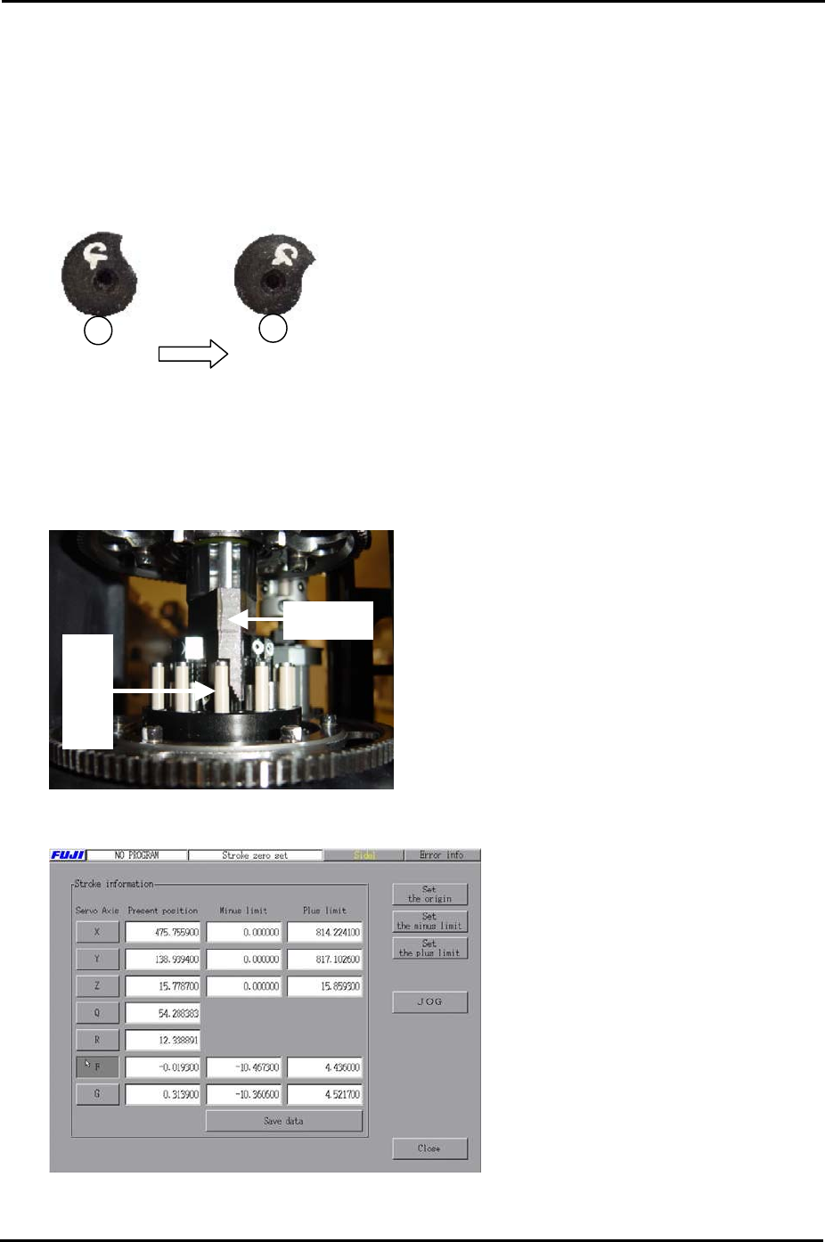
2. Set the G and F axes at the following position:
Fig. 1 Fig. 2
When releasing the index cam f
the position in Fig.1, it stops at the
position in fig.2. This is the upper
resting position.
rom
3. Set the R axis so that the number 1 nozzle piston is facing straight out towards the front
of the machine at side 1.
4. With the R axis set as described in step 3 set the Q axis so that the pusher is up against
the nozzle number 1 air blow pin, as shown in the photo below:
Pusher
Air blow pin
5. Select [Maintenance C] – [Stroke Zero Set] to display the following screen:
6. Select the servo axis you are setting and then click [Set the origin] to set the servo
counter to zero.
SMT Equipment Quality Assurance Dept.
2 – 5 CS Section
FK-9F98-34 XP Type II Series Training Text for Service Engineers
Edition 2.0 XP142E – Chapter 2 Origin settings Page 6 of 6
Fuji Machine Mfg. Co., Ltd. Okazaki
7. Also check that the minus limits for the X, Y, and Z axes are set to zero.
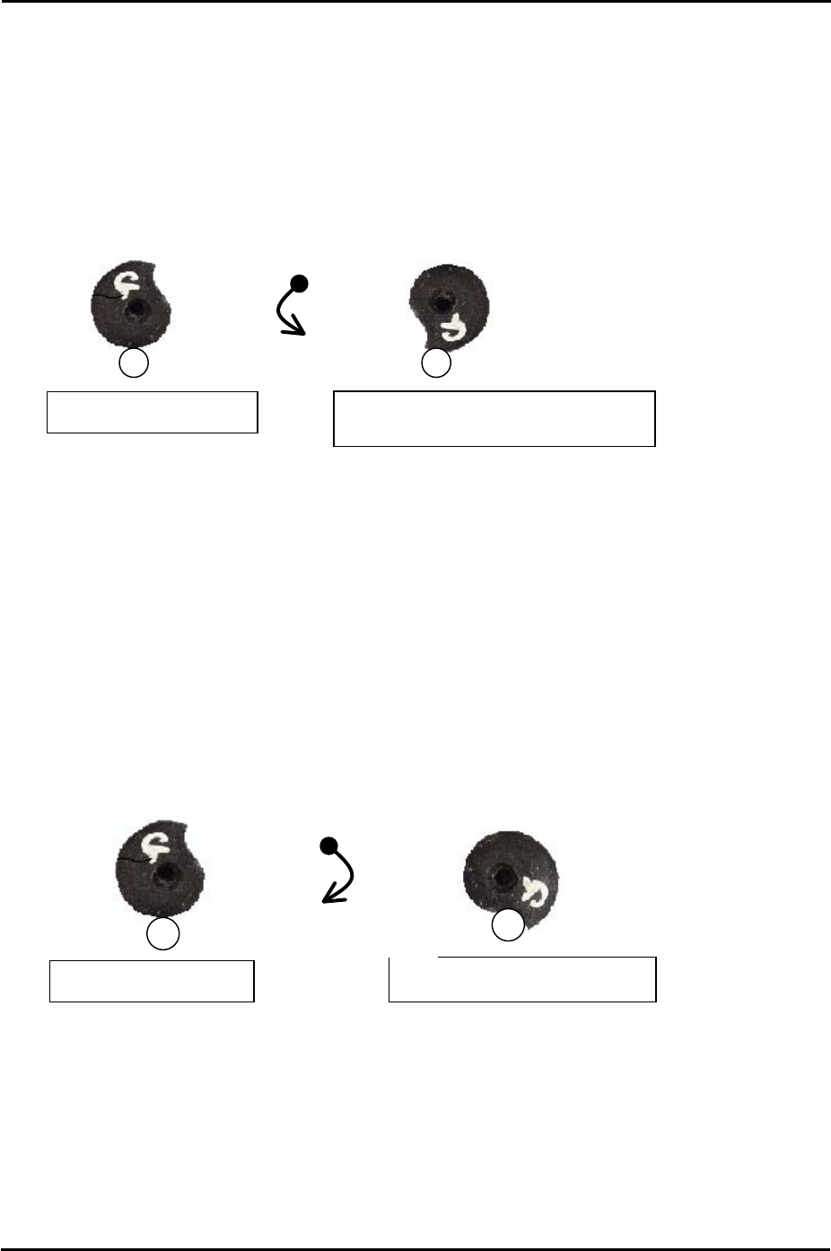
2.6 Setting the Minus Software Limits
1. To set the F and G axis minus limits set the cam at the upper resting position and then
rotate anti-clockwise until the cam is at the position just before it flips over the roller, this
is known as the lower resting position.
2. At this position select [Maintenance C] – [Stroke Zero Set] – and select the F and G axes
before pressing [Set the minus limit] to save the current counter value to proper data.
2.7 Setting the Plus Software Limits
1. Press the emergency stop button to cut the 200-volt power supply to the servos.
2. Set the X, Y and Z axes against the plus mechanical stoppers.
3. Set the F and G axes indexing cams at the upper resting position and then rotate
clockwise until the cam contacts the roller and cannot rotate any further.
Counterclockwise
rotation
Lower resting position (Minus Limit)
Clockwise rotation
Upper limit resting position
Upper resting position
Upper resting position
4. At this position select [Maintenance C] – [Stroke Zero Set] and select the axis you are
setting before pressing [Set the plus limit].
SMT Equipment Quality Assurance Dept.
2 – 6 CS Section

C
C
h
h
a
a
p
p
t
t
e
e
r
r
3
3
S
S
t
t
a
a
t
t
i
i
c
c
A
A
c
c
c
c
u
u
r
r
a
a
c
c
y
y
M
M
e
e
a
a
s
s
u
u
r
r
e
e
m
m
e
e
n
n
t
t