XP Type II 工程师培训手册 (2.0).pdf.pdf - 第54页
FK-9F98-34 XP T ype II Series T raining T ext for Service Engineers Edition 2.0 XP142E – Chapter 5 Peripheral Adjustm ents Page 10 of 14 5.6 MFU Cylinder Sensors 1. Note that there are two sensors on each clamping cylind…
FK-9F98-34 XP Type II Series Training Text for Service Engineers
Edition 2.0 XP142E – Chapter 5 Peripheral Adjustments Page 9 of 14
5.5 Feeder Set Check Sensors
Feeder
Set Chec
k
Sensor
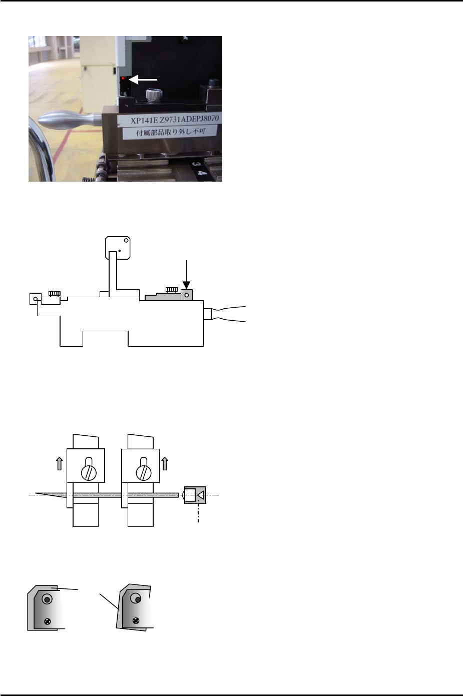
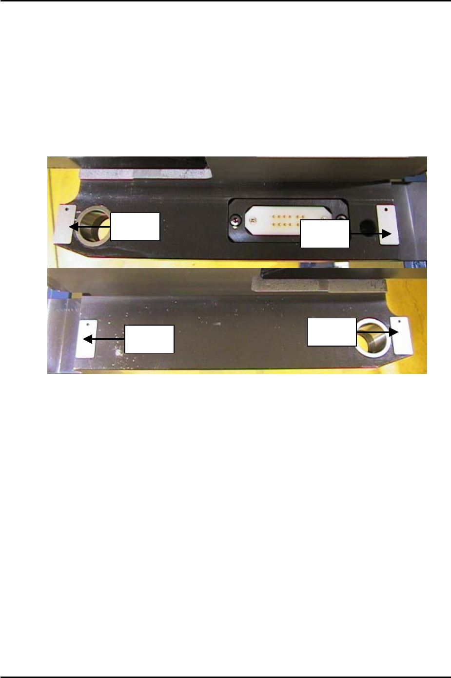
1. Clamp the MFU and set two sensor adjustment jigs (Z9631ADEPJ8070) at slots D47
and D49 at side 1.
Rear Sliding
A
ttachment
Z9631ADEPJ8070
2. Fix the rear sliding attachments at their forward limit (in the direction towards the
machine interior) and insert a 1.8mm diameter wire jig between the holes in the
attachments. Adjust the feeder set check sensor position so that the point where the
sensor beam is emitted is aligned with the center of the wire jig.
D47
D49
Feeder set check sensor
3. Check the tilt of both sensors.
BKT
Sensor
BKT
4. Use I/O [X017] Side1XYAxisInter to monitor the signal.
5. Repeat for side 2 using I/O [X01A] Side2XYAxisInter to monitor the signal.
Fuji Machine Mfg. Co., Ltd. Okazaki
SMT Equipment Quality Assurance Dept.
5 – 9 CS Section
FK-9F98-34 XP Type II Series Training Text for Service Engineers
Edition 2.0 XP142E – Chapter 5 Peripheral Adjustments Page 10 of 14
5.6 MFU Cylinder Sensors
1. Note that there are two sensors on each clamping cylinder, making a total of four sensors
on side 1, and four sensors on side 2.
2. The clamp check sensors (X02E side1MfuUpChk) should be adjusted so that they are
ON 0.3mm from the clamp upper limit, and OFF 0.8mm from the clamp upper limit. In
order to adjust them, please follow the procedure below:
3. Place 0.3mm spacers in the four corners of the MFU clamping surface as illustrated
below:
Spacer
Spacer
Spacer
Spacer
4. Clamp the MFU.
5. Slide the clamp check sensors DOWN until they go OFF then slide them back UP until
they just come ON then tighten the screw (X02E side1MfuUpChk).
6. Unclamp the MFU and replace the 0.3mm spacers with 0.8mm spacers.
7. Clamp the MFU and confirm that the clamp check sensors (X02E side1MfuUpChk) are
OFF.
8. Unclamp the MFU and slide the unclamp check sensors UP until they go OFF and then
slide them back DOWN until they come ON. From the position they first come ON slide
them a further 1mm DOWN and tighten the screw. (X02F side1MfuDownChk).
9. Repeat the procedure for side 2 (X03E side2MfuUpChk) and (X03F side2MfuDownChk).
Fuji Machine Mfg. Co., Ltd. Okazaki
SMT Equipment Quality Assurance Dept.
5 – 10 CS Section

FK-9F98-34 XP Type II Series Training Text for Service Engineers
Edition 2.0 XP142E – Chapter 5 Peripheral Adjustments Page 11 of 14
5.7 Waste Tape Cutter
WARNING: the waste tape cutter plate is an extremely heavy item. Please handle with care.
Also, take extreme caution when handling (or working in the vicinity of) the cutter blade. It
may cause damage or personal injury.
1. Remove the MFU, and the waste tape cutter cover.
2. For the waste tape cutter cylinder air valve speed controller adjustments please refer to
the following table:
Speed controller Air Tube Line Number of turns from fully closed
Cutter close valve U5 7.5
Cutter open valve U6 8
3. Repeat the procedure for the side 2 cutter.
Cutter Engagement Adjustment
1. Disconnect the air supply to the machine and pull out the two air tubes that supply air to
the tape cutter cylinder. This will allow you to operate the tape cutter manually.
2. Ensure the gap between the movable cutter topside and the fixed cutter underside is
within 0 to 0.03mm when both cutters are engaged.
3. Ensure there are no nicks or cracks in the cutter blade.
4. Repeat the procedure for the side 2 cutter.
Stopper Position Adjustment
1. Loosen the stopper and position it just at the end of the cylinder stroke.
2. Lock the stopper 1.5 to 2.0mm in from this position.
3. This procedure should be carried out for both the cutter close stopper and the cutter open
stopper.
4. Repeat the procedure for the side 2 cutter.
Retract Limit Sensor Adjustment
1. With the stopper adjustment complete, adjust the side 1 retract limit sensor so that when
the cutter is moved to its retract limit the I/O (Y031 Side1TpCutOrgPos) comes ON
1.5mm in from the cylinder stroke end.
2. Repeat the procedure for the side 2 cutter (Y033 Side2TpCutOrgPos).
Fuji Machine Mfg. Co., Ltd. Okazaki
SMT Equipment Quality Assurance Dept.
5 – 11 CS Section