XP Type II 工程师培训手册 (2.0).pdf.pdf - 第167页
FK-9F98-34 XP T ype II Series T raining T ext for Service Engineers Edition 2.0 XP242E – Chapter 6 Proper Data Mea surement s Page 12 of 30 Prism Position 1. Once the camera center has been adjusted the image on the disp…
FK-9F98-34 XP Type II Series Training Text for Service Engineers
Edition 2.0 XP242E – Chapter 6 Proper Data Measurements Page 11 of 30
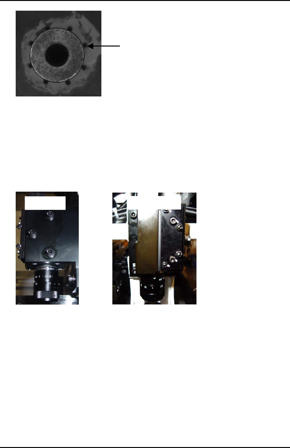
The holes around
the nozzle jig should
be evenly balanced.
Vertical Cross Hair
1. To set the vertical cross hair in the center of the nozzle jig, adjust the position of the
camera in the X-direction.
2. Loosen bolts 1, 2 and 3 shown in the photo below:
Side View
5
4
2
3
1
Front View
3. Unlock the nuts on the hollow bolts 4 and 5 shown above.
4. Use the hollow bolts to adjust the position of the camera in the X-direction so that
the vertical cross hair comes to the center of the nozzle jig.
5. Check that the holes around the nozzle jig are evenly balanced. To avoid tilting the
camera always rotate the two hollow bolts by the same amount.
6. Once the camera center has been set lock all bolts.
Fuji Machine Mfg. Co., Ltd. Okazaki.
SMT Equipment Quality Assurance Dept.
6 – 11 CS Section
FK-9F98-34 XP Type II Series Training Text for Service Engineers
Edition 2.0 XP242E – Chapter 6 Proper Data Measurements Page 12 of 30
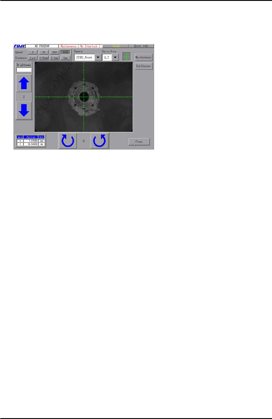
Prism Position
1. Once the camera center has been adjusted the image on the display should be
similar to the one below:
2. At this position record the Y-axis servo counter and then select [Maintenance] –
[Proper Data Editor] – [Prizm Position] – [PrismFront/Prism Back] and manually
input the Y counter value.
Fuji Machine Mfg. Co., Ltd. Okazaki.
SMT Equipment Quality Assurance Dept.
6 – 12 CS Section
FK-9F98-34 XP Type II Series Training Text for Service Engineers
Edition 2.0 XP242E – Chapter 6 Proper Data Measurements Page 13 of 30
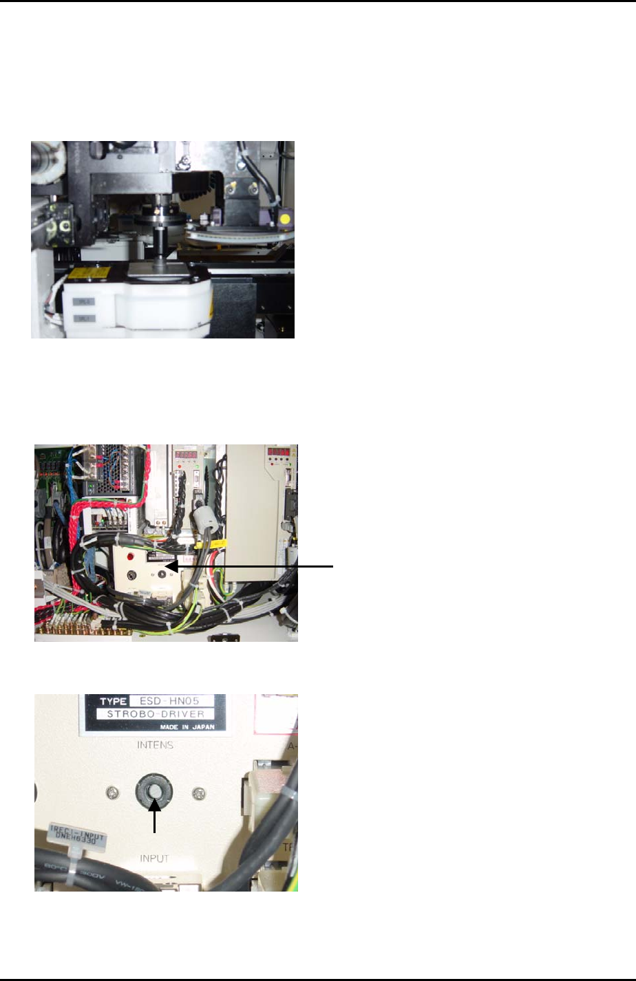
6.7 Parts Camera Brightness
1. Put a 15mm or 20mm nozzle on the placing head.
2. Put the colour sample on the nozzle with the grey surface facing downwards and
move it to the prism position.
3. Bring the Z-axis to the vision processing height: Z0 + 27.5 + 0.5mm (0.5mm is
equivalent to the thickness of the colour sample).
4. Locate the strobe light power source in the side1 electrical box.
Strobe light
power source
5. Use a minus driver to turn the “INTENS” volume screw fully clockwise
Volume Adjustment
Fuji Machine Mfg. Co., Ltd. Okazaki.
SMT Equipment Quality Assurance Dept.
6 – 13 CS Section