XP Type II 工程师培训手册 (2.0).pdf.pdf - 第158页
FK-9F98-34 XP T ype II Series T raining T ext for Service Engineers Edition 2.0 XP242E – Chapter 6 Proper Data Mea surement s Page 3 of 30 4. Confirm that the two LED lights for A and B are ON: A B 5. With the mark camer…
FK-9F98-34 XP Type II Series Training Text for Service Engineers
Edition 2.0 XP242E – Chapter 6 Proper Data Measurements Page 2 of 30
5. Set the height of the camera so that the clearance between the bottom of the
lighting unit and the plate jig is greater than 61 mm (61.5mm is ideal). This is to
ensure that there is sufficient clearance between the lighting unit and the nozzle
change platform.
6. Select [Maintenance A] – [JOG] and [Fiducial]. The light comes ON for the mark
camera, and the live image is displayed on the monitor.
7. Adjust the focus ring on the mark camera so that the markings on the plate jig come
into clear, sharp focus.
8. Apply adhesive (Loctite 425) to the hollow bolts and lock the lens.
9. Remove the light source unit.
10. Install the lens cover.
11. Replace the light source unit right up against the lip of the camera installation
bracket.
12. Set the position of the lens cover so that there is 0.5mm clearance between the
bottom of the lens cover and the top of the light source unit:
0.5mm
Camera Brightness Measurement
1. The lighting unit contains two different light sources. One (light source A) is the ring
of diodes at the bottom of the unit. The other (light source B) is the rectangular light
emitter found above the ring of diodes.
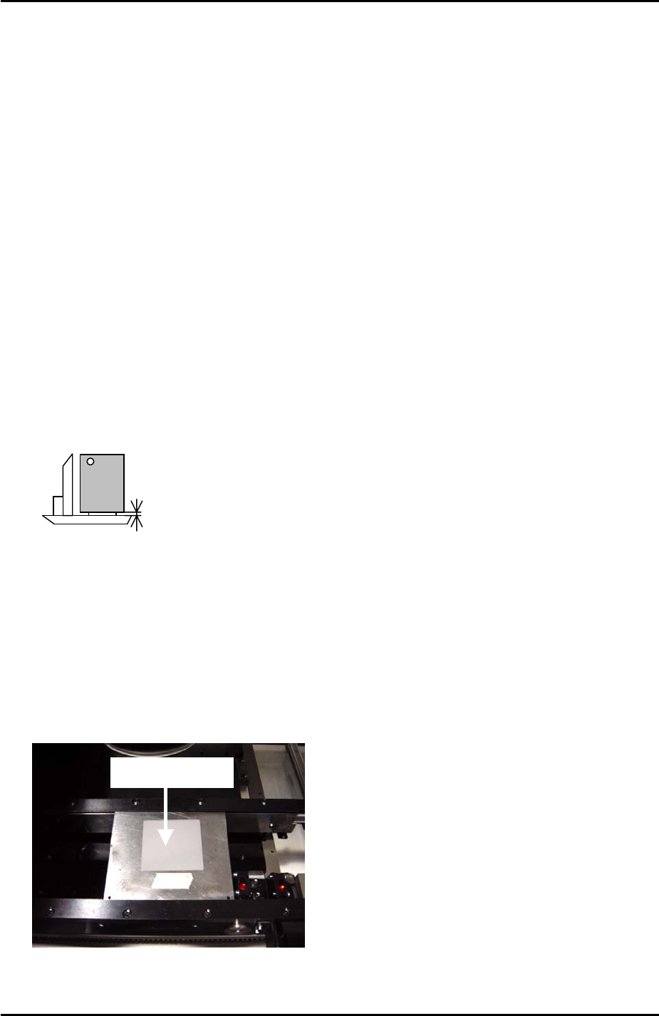
2. Place the color sample on the mark camera jig plate and bring the mark camera
above the disc.
Color Sample
3. Select [Maintenance A] – [Jog] – [Fiducial].
Fuji Machine Mfg. Co., Ltd. Okazaki.
SMT Equipment Quality Assurance Dept.
6 – 2 CS Section
FK-9F98-34 XP Type II Series Training Text for Service Engineers
Edition 2.0 XP242E – Chapter 6 Proper Data Measurements Page 3 of 30
4. Confirm that the two LED lights for A and B are ON:
A
B
5. With the mark camera centered on the color sample touch the screen to display a
brightness reading.
6. Adjust the camera gain so that the brightness becomes 120 +/-10.
6.2 Mark Camera Resolution
Equipment: Glass gage for mark camera resolution measurement (Z3502DFAJ0020).
1. Clamp the glass gage in the main table. Ensure it is flush with the reference rail.
Push the glass gauge against the
reference rail and clamp the gauge.
The glass gauge should be
printed side up.
The reference rail
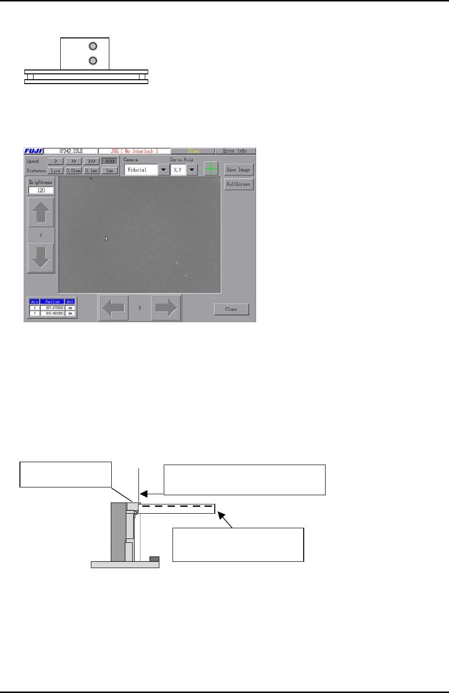
2. Select [Maintenance A] – [Jog] – [Fiducial] to display the mark camera live image.
3. Bring the mark camera above the center of the glass gage and select the cross
hairs.
Fuji Machine Mfg. Co., Ltd. Okazaki.
SMT Equipment Quality Assurance Dept.
6 – 3 CS Section
FK-9F98-34 XP Type II Series Training Text for Service Engineers
Edition 2.0 XP242E – Chapter 6 Proper Data Measurements Page 4 of 30
4. Inch the mark camera until it is centered on the center dot in the image:
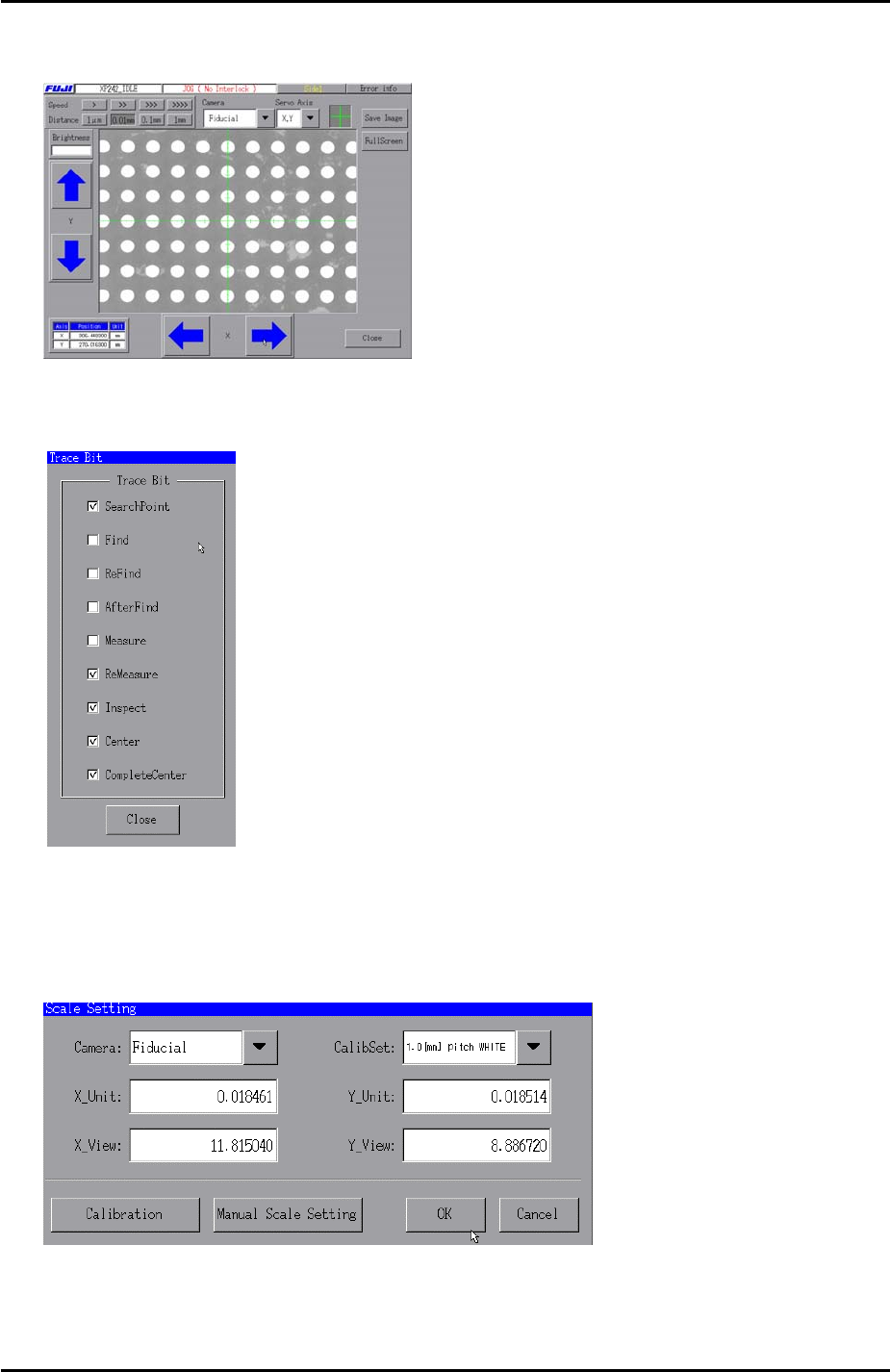
5. Select [Maintenance A] – [Trace Bit] and select “SearchPoint”, “ReMeasure”,
“Inspect”, “Center”, and “Complete Center”as shown below:
6. Press [Close] to return to the [Maintenance A] screen and select [Scale Setting].
7. Select “Fiducial” from the [Camera] drop down list and “1.0 [mm] pitch WHITE” from
the [CalibSet] drop down list as shown below:
8. Select [Calibration] and answer YES to the question “Set Center?” and the
resolution measurement will proceed.
Fuji Machine Mfg. Co., Ltd. Okazaki.
SMT Equipment Quality Assurance Dept.
6 – 4 CS Section