XP Type II 工程师培训手册 (2.0).pdf.pdf - 第216页
FK-9F98-34 XP T ype II Series T raining T ext for Service Engineers Edition 2.0 XP242E – Chapter 9 Options Page 4 of 12 9.2 Coplanarity Camera Adjustment Equipment 1. Coplanarity Jig (Z9631DEPJ3410). Camera Setting 1. Se…
FK-9F98-34 XP Type II Series Training Text for Service Engineers
Edition 2.0 XP242E – Chapter 9 Options Page 3 of 12
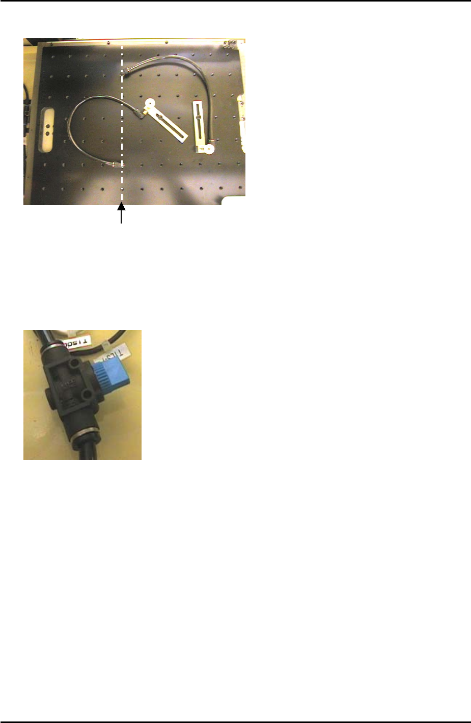
Only holes in this
line have a vacuum
backup air supply
3. An air valve can be used to switch the vacuum backup air supply ON and OFF.
Fuji Machine Mfg. Co., Ltd. Okazaki
SMT Equipment Quality Assurance Dept.
9 – 3 CS Section

FK-9F98-34 XP Type II Series Training Text for Service Engineers
Edition 2.0 XP242E – Chapter 9 Options Page 4 of 12
9.2 Coplanarity Camera Adjustment
Equipment
1. Coplanarity Jig (Z9631DEPJ3410).
Camera Setting
1. Set the coplanarity camera aperture to 8 and lock the hollow bolt with Loctite 425.
Proper Data Setting
1. Select [Maintenance C] – [Proper Data Editor] – [MACHINE_TYPE] – and set
[Coplanarity] to 1.
2. Select [OTHERS] and set the following proper data items:
Proper Data Item Setting
X_CoplanarityPosX 625
Y_CoplanarityPosY Same as [PrismBack] position
Z_CoplanarityPosZ 41
CoplaCamShutterSpeed 3500
Vision Processing Position
1. Make sure that there is a 2.5mm diameter nozzle in the nozzle station and in the
nozzle editor.
2. Select [Maintenance C] – [Custom Maintenance] and select the [Coplanarity] camera
from the camera drop down list.
3. Select [Maintenance] – [Focus adjustment] – and press and hold down the [START]
button until the “Manually Pick-Up the focus jig” message appears.
4. Press [OK] – [Focus adjustment] and press and hold down the [START] button until
the “Move” message displays. The nozzle is now at the vision processing position.
5. Press [OK] – [Complete] and the following message displays:
6. Press [OK] – [Close] and the following message displays:
Fuji Machine Mfg. Co., Ltd. Okazaki
SMT Equipment Quality Assurance Dept.
9 – 4 CS Section
FK-9F98-34 XP Type II Series Training Text for Service Engineers
Edition 2.0 XP242E – Chapter 9 Options Page 5 of 12
7. Select [OK] – [Return] to exit the focus adjustment but remain in the maintenance
mode screen.
8. Press the E-stop button to cut the 200Volt power supply to the servos. Be careful not
to move the X, Y and Z axes as they are now at the coplanarity vision processing
position.
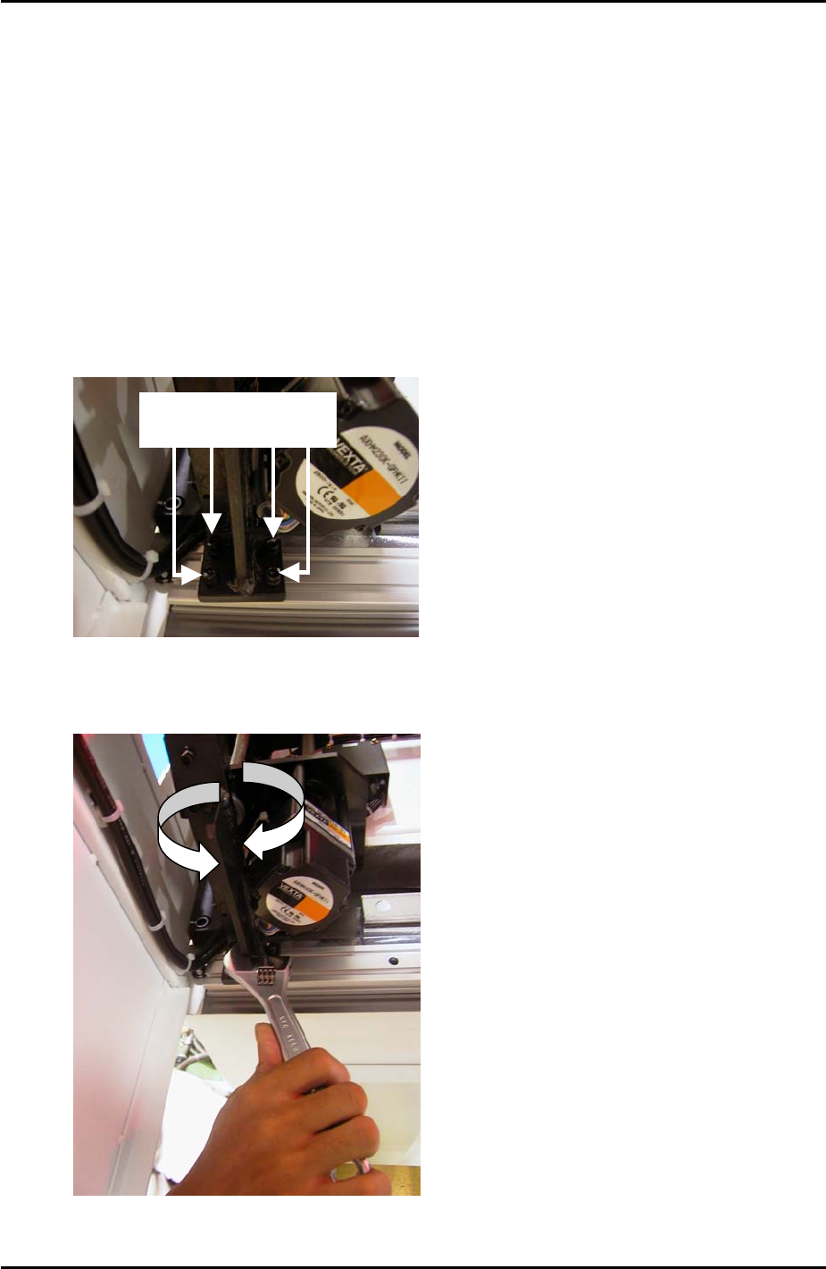
Camera Centering
Vertical Cross Hair
1. Select the cross hairs and then roughly adjust the focus so that the image of the
nozzle on the screen is clear and sharp.
2. Loosen the following 4 bolts on the base of the coplanarity camera bracket:
Loosen these 4 bolts
3. Adjust the orientation of the bracket until the nozzle is aligned with the vertical cross
hair (make sure there is a gap between the bracket and the conveyor motor):
Fuji Machine Mfg. Co., Ltd. Okazaki
SMT Equipment Quality Assurance Dept.
9 – 5 CS Section