XP Type II 工程师培训手册 (2.0).pdf.pdf - 第23页
FK-9F98-34 XP T ype II Series T raining T ext for Service Engineers Edition 2.0 XP142E – Chapter 2 Origin settings Page 4 of 6 Fuji Machine Mfg. Co., Ltd. Okazaki 13. Af ter resetting the amplifier set the axis origin by…

FK-9F98-34 XP Type II Series Training Text for Service Engineers
Edition 2.0 XP142E – Chapter 2 Origin settings Page 3 of 6
Fuji Machine Mfg. Co., Ltd. Okazaki
5. Use the UP and DOWN arrow keys to set the entry to Pn000.
6. Use the LEFT and RIGHT arrow keys to select the “0” furthest to the right of the “Pn000”
entry. Check the parameter value for Pn000.
7. Use the UP arrow key to select the next entry “Pn001” and check the parameter value for
that entry.
8. Continue using the UP arrow key to check all servo parameters on the servo amp
parameter list (the most recent list at the time of publication can be found in the
supplementary section of this manual, however always check to see if the list has been
updated).
9. If it is necessary to change one of the parameter values press the [DATA] key on the
digital operator.
10. Use the arrow keys to change the value and then press [DATA] again to return.
2.3 Resetting the X, Y, F and G Servo Amplifiers
1. The amplifiers must be reset in the following cases:
• An amplifier is replaced or removed.
• A motor is replaced or removed.
• An encoder cable is replaced or removed.
• An axis tension belt is replaced or removed.
• An axis pulley is replaced or removed.
2. Press the emergency stop button and set the relevant axis at its origin position (X and Y
are set against their minus mechanical stopper, for details of the origin position for F and
G refer to “2.5 Setting the Axis Origins”.
3. Connect a digital operator to the target amplifier (“bb” or error code displays).
4. Press [DSPL/SET] to select the “Fn000” channel mode.
5. Press the [▲] arrow key to select channel “Fn008”.
6. Press [DATA/ENTER] to display “PGCL1”.
7. Press the [▲] arrow key to set it to “PGCL5”.
8. Press [DSPL/SET] and “done” displays.
9. Press [DATA/ENTER] to return to channel “Fn008”.
10. Press the [▼] arrow key to return to “Fn000”.
11. Press [DSPL/SET] to return to the original display.
12. Remove the digital operator from the target amplifier and restart the machine.
SMT Equipment Quality Assurance Dept.
2 – 3 CS Section

FK-9F98-34 XP Type II Series Training Text for Service Engineers
Edition 2.0 XP142E – Chapter 2 Origin settings Page 4 of 6
Fuji Machine Mfg. Co., Ltd. Okazaki
13. After resetting the amplifier set the axis origin by following the procedure described in
“2.5 Setting the Axis Origins”.
2.4 Resetting the R, Q, and Z Servo Amplifiers
1. The amplifiers must be reset in the following cases:
• An amplifier is replaced or removed.
• A motor is replaced or removed.
• An encoder cable is replaced or removed.
• An axis tension belt is replaced or removed.
• An axis pulley is replaced or removed.
2. Press the emergency stop button and set the relevant axis at its origin position (Z is set
against its minus mechanical stopper, for details of the origin position for R and Q refer to
“2.5 Setting the Axis Origins”).
3. Connect a digital operator (JUSP-OPO5A) to the target amplifier.
4. Press [MODE/SET] and select the “Fn000” channel mode.
5. Press the [▲▼] arrow keys to select channel “Fn008”.
6. Press [DATA] to display the “Multiturn Clear“ screen “PGCL1”.
7. Press the [▲] arrow key to set it to “PGCL5”.
8. Press [DATA] to reset the amplifier.
9. Press [MODE/SET] 3 times to return to the original screen.
10. Remove the digital operator from the target amplifier and restart the machine.
11. After resetting the amplifier set the axis origin by following the procedure described in
“2.5 Setting the Axis Origins”.
SMT Equipment Quality Assurance Dept.
2 – 4 CS Section
FK-9F98-34 XP Type II Series Training Text for Service Engineers
Edition 2.0 XP142E – Chapter 2 Origin settings Page 5 of 6
Fuji Machine Mfg. Co., Ltd. Okazaki
2.5 Setting the Axis Origins
1. Press the emergency stop button to cut the 200-volt power supply to the servos, then
set the X, Y and Z axes against their minus mechanical stoppers. For details of the
location of mechanical stoppers please refer to the diagrams in the “Supplementary
Information” section of this manual.
2. Set the G and F axes at the following position:
Fig. 1 Fig. 2
When releasing the index cam f
the position in Fig.1, it stops at the
position in fig.2. This is the upper
resting position.
rom
3. Set the R axis so that the number 1 nozzle piston is facing straight out towards the front
of the machine at side 1.
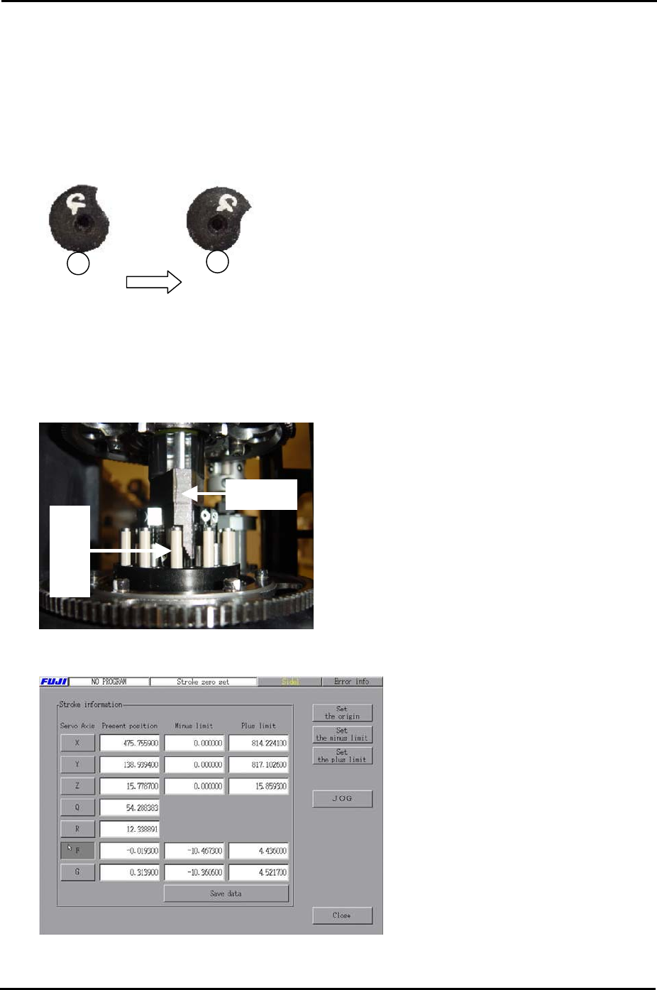
4. With the R axis set as described in step 3 set the Q axis so that the pusher is up against
the nozzle number 1 air blow pin, as shown in the photo below:
Pusher
Air blow pin
5. Select [Maintenance C] – [Stroke Zero Set] to display the following screen:
6. Select the servo axis you are setting and then click [Set the origin] to set the servo
counter to zero.
SMT Equipment Quality Assurance Dept.
2 – 5 CS Section