XP Type II 工程师培训手册 (2.0).pdf.pdf - 第122页
FK-9F98-34 XP T ype II Series T raining T est for Service Engineers Edition 2.0 XP242E – Chapter 3 S t atic Accuracy Me asurement Page 4 of 6 3.4 Nozzle Holder Surface 1. Equipment: Lever type dial gauge (0.002mm). Face …
FK-9F98-34 XP Type II Series Training Test for Service Engineers
Edition 2.0 XP242E – Chapter 3 Static Accuracy Measurement Page 3 of 6
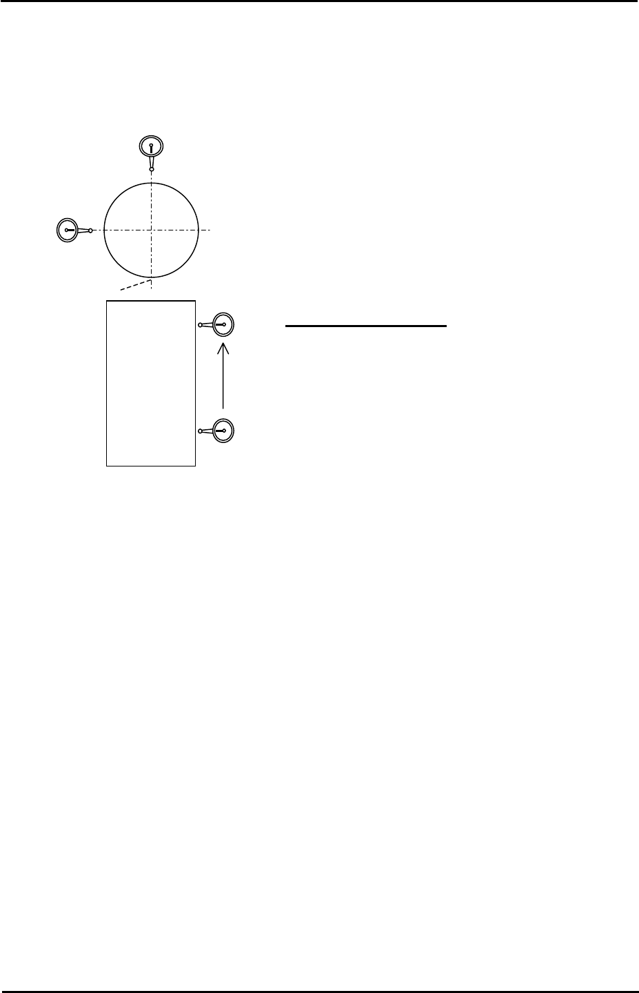
5. Set a mini magnetic dial gauge stand on the placing head at the end of the Z axis spline
shaft. Set the tip of the dial indicator on the most forward part of the cylindrical jig vertical
surface (point C in the diagram below).
C
30mm
Z9531DEPJ0060
0
A
X-direction
Y-direction
Tolerance 0.030 / 30mm
6. Measure the straightness of the Z-axis. The range of measurement is from 2mm above
the minus stopper to 32mm above the minus stopper (a stroke of 30mm).
7. The difference in straightness between these two points should be within 0.03mm.
8. Repeat for the right hand side of the cylindrical jig.
Fuji Machine Mfg. Co., Ltd. Okazaki
SMT Equipment Quality Assurance Dept.
3 – 3 CS Section
FK-9F98-34 XP Type II Series Training Test for Service Engineers
Edition 2.0 XP242E – Chapter 3 Static Accuracy Measurement Page 4 of 6
3.4 Nozzle Holder Surface
1. Equipment: Lever type dial gauge (0.002mm).
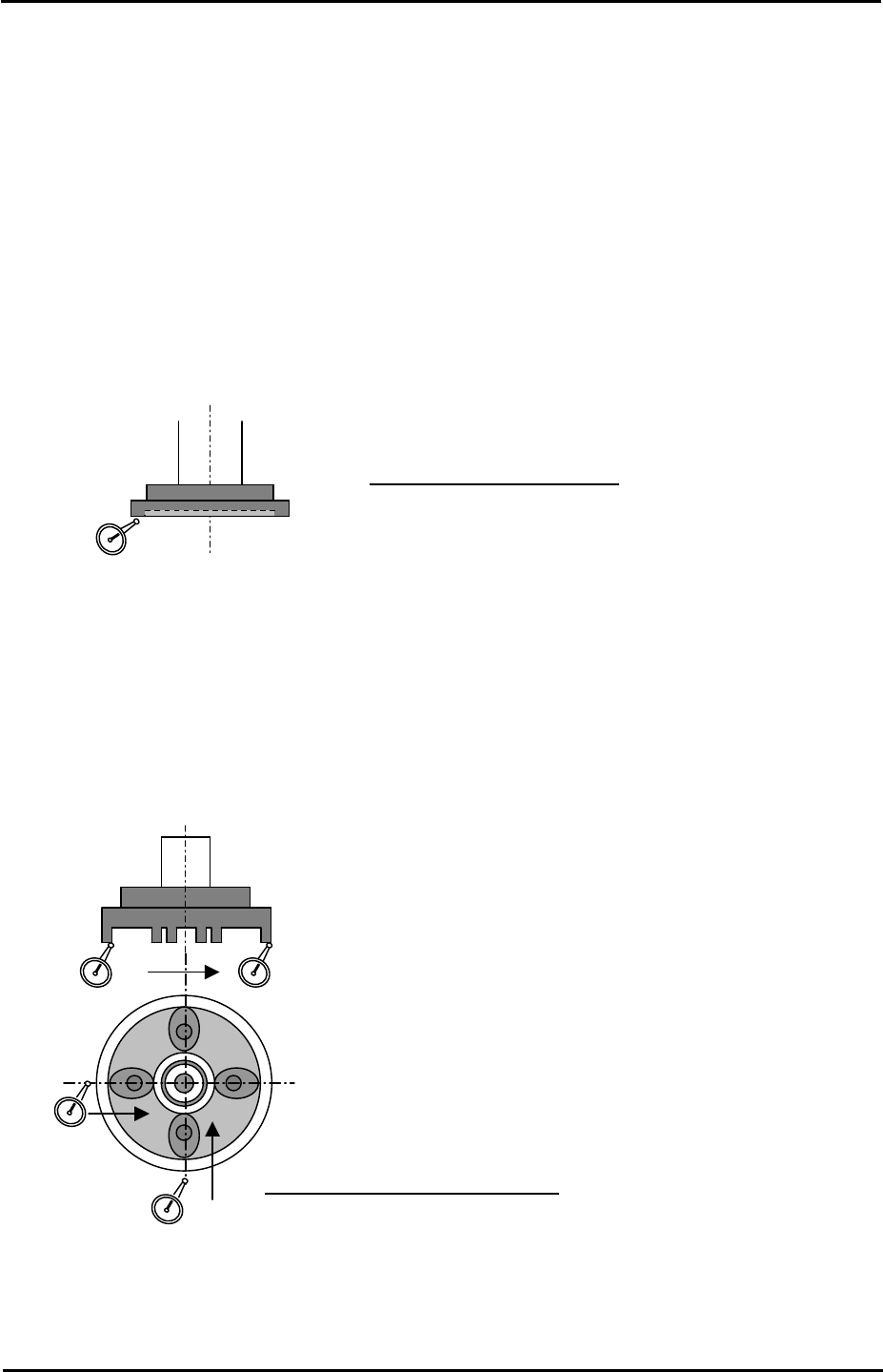
Face oscillation measurement
1. Position the Z axis 2 mm above the Z-axis minus stopper.
2. Put a dial indicator against the underside of the nozzle holder and measure the surface
oscillation by turning the Q-axis through 360 degrees.
Nozzle pick-up surface parallelism measurement
Tolerance: 0.02mm / 360°
1. Position the nozzle pick-up surface 2 mm above the Z-axis minus stopper.
2. Set a dial gauge on the underside of the nozzle holder, and measure the difference in
flatness from one side to the other. Measure in both the X and the Y-direction.
Tolerance: +/- 0.020mm / 50mm
Fuji Machine Mfg. Co., Ltd. Okazaki
SMT Equipment Quality Assurance Dept.
3 – 4 CS Section
FK-9F98-34 XP Type II Series Training Test for Service Engineers
Edition 2.0 XP242E – Chapter 3 Static Accuracy Measurement Page 5 of 6
3.5 Nozzle Station Parallelism and Flatness
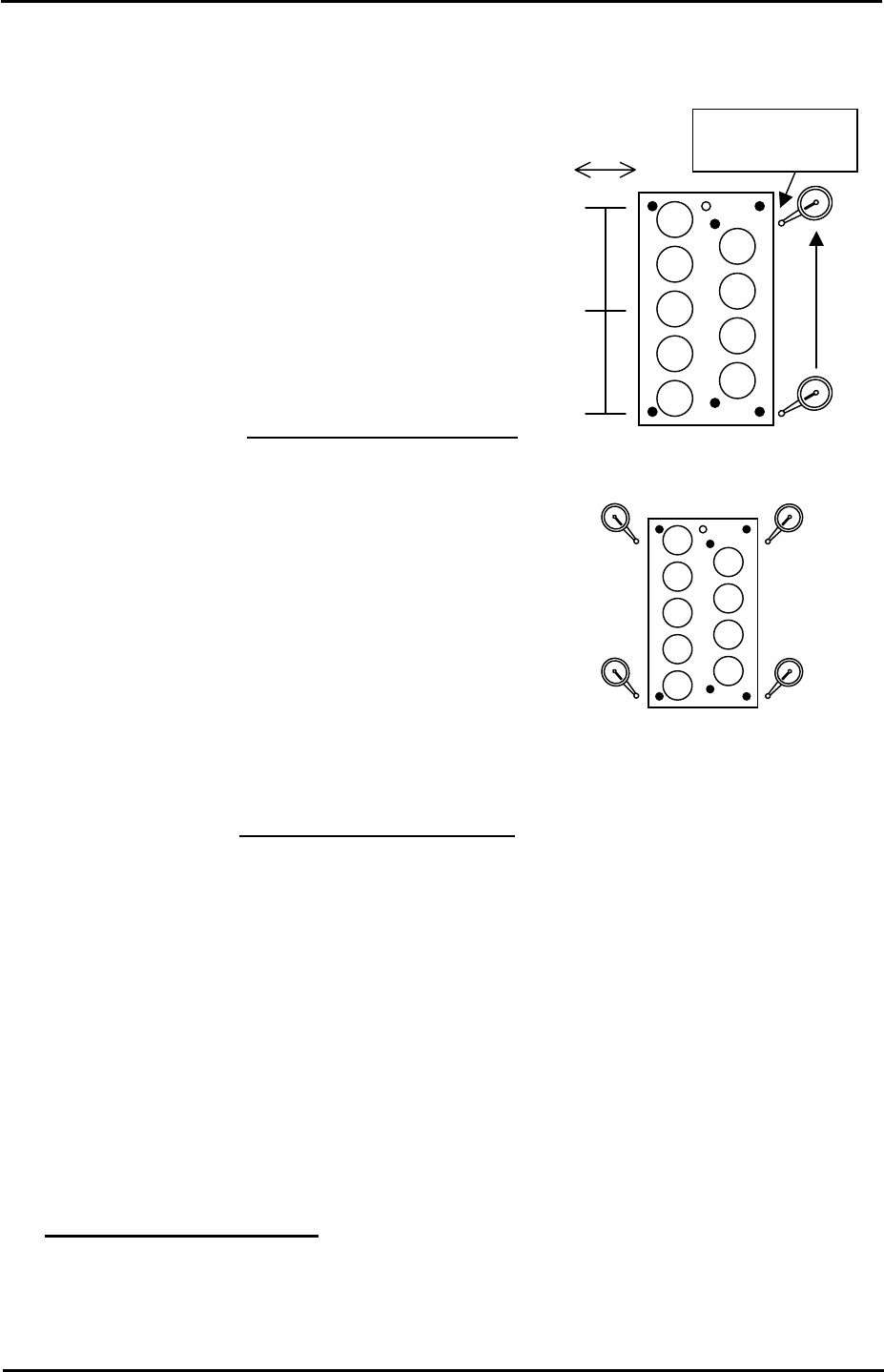
Nozzle station parallelism measurement
1. Attach a dial gauge to the placing head (an
extension bar necessary).
2. Measure the parallelism from the reference
position in the X- and Y-direction.
Note: if the value is out of the tolerance, please
contact FUJI.
Nozzle station flatness measurement
+-
0
Measure the side of
the nozzle station
0
140
280
Tolerance: 0.06mm / 280mm
B
A
D
C
1. Attach the dial gauge to the placing head (an extension
bar is necessary).
2. Measure the height of the four corners of the nozzle
station, ensuring any deviation is within 0.06 mm.
Note: If the value is out of the tolerance, please contact
FUJI.
0
Tolerance: Deviation 0.06mm
3.6 Backlash
• Equipment: Lever type dial gauge (0.002mm).
1. Set the dial gauge to the X and Y-axes. Turn the 200V servo power ON. Measure any
backlash in the X and Y axes movement.
2. For the Q-axis, adjust it so there is no backlash.
Tolerance: within 0.010 mm
Fuji Machine Mfg. Co., Ltd. Okazaki
SMT Equipment Quality Assurance Dept.
3 – 5 CS Section